CORDIC-Based QPSK Carrier Synchronization
This model shows the use of a CORDIC (COordinate Rotation DIgital Computer) rotation algorithm in a digital PLL (Phase Locked Loop) implementation for QPSK carrier synchronization. Fixed-Point Designer™ is needed to run this model.
Introduction
The structure of a digital PLL is essentially equivalent to that of a continuous-time PLL. A PLL has the following components: a phase error detector (PED), a loop filter, and a controlled oscillator.
In the case of QPSK carrier (phase and frequency) synchronization, implementing the loop filter as a digital P+I (proportional-plus-integrator) filter produces a second order PLL. The controlled oscillator (Phase Accumulator) adjusts the angle of the received QPSK signal via a complex rotation.
You can implement the complex rotation using a variety of approaches, including direct complex multiplication by exp(j*theta). However, such an implementation can be relatively expensive in terms of hardware (e.g., FPGA or ASIC) resources. An alternative approach uses a CORDIC-based rotation algorithm to implement the complex multiplication. This example uses this approach, via the Fixed-Point Designer™ CORDICROTATE function. This results in a multiplier-less complex rotation approximation, where the trade-off is in terms of speed. A small number of CORDIC iterations may often be enough to achieve a good digital PLL response, without the full hardware resource cost of a true complex multiplication.
Structure of the Example


Tx Data Source
The PN Sequence Generator library block from the Communications Toolbox™ is the Tx Data Source, generating unsigned 2-bit integer symbols.
QPSK Modulator
The QPSK Modulator Baseband library block from the Communications Toolbox uses a pi/4 phase offset and binary ordering to compute signed 12-bit fixed-point modulator output values.
Raised Cosine Tx Filter
The Raised Cosine Transmit Filter library block from the Communications Toolbox performs square root FIR filtering with an upsampling factor of 8.
Transmitter Impairments
The Phase/Frequency Offset library block from the Communications Toolbox simulates the associated transmitter impairments. You can tune the Phase offset and Frequency offset parameter values to see the effect on the PLL Phase Error time scope and the receive signal scatter plot displays.
AWGN Channel
The AWGN Channel library block from the Communications Toolbox simulates a noisy channel. You can tune the block Eb/No parameter to see the effect on the PLL Phase Error time scope and the receive signal scatter plot displays.
Raised Cosine Rx Filter
The Raised Cosine Receive Filter library block from the Communications Toolbox performs square root FIR filtering with a downsampling factor of 8.
CORDIC-Based PLL Subsystem
The CORDIC-Based PLL subsystem consists of a Phase Error Detector (PED), P+I Loop Filter, Phase Accumulator, and CORDICROTATE to form the corrected complex signal output values.
CORDIC-Based PLL

Phase Error Detector
The Phase Error Detector is implemented using a MATLAB® function.

P+I Loop Filter
A P+I Loop Filter implements a second order PLL. The loop constants K1 (P gain) and K2 (I gain) are derived from the Normalized loop bandwidth and Damping factor parameters of the masked CORDIC-Based PLL subsystem.

Phase Accumulator
The Phase Accumulator computes the angle Theta.

CORDICROTATE
The MATLAB function CORDICROTATE rotates the complex received signal by Theta using an iterative, multiplier-less, CORDIC-based algorithm.

Results and Displays
Phase Error
Use the Phase Error time scope block to view the time-varying PLL Phase Error Detector output values.

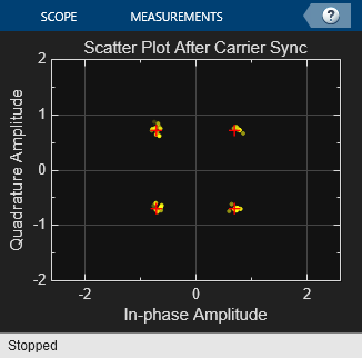
Scatter Plots
Use the Before Carrier Synchronization and After Carrier Synchronization scope blocks to observe the effects of tuning the Transmitter Impairments and AWGN Channel parameters.


Experimenting with the Example
Transmitter Impairments
To see the effects of transmitter phase and frequency offset impairments, change the Phase offset and Frequency offset parameter values while the model is running. Set the model StopTime to inf and use the PLL Enable/Disable switch to observe changes in the transient response.
AWGN Channel
To see the effects of a noisy channel, change the Eb/No parameter value while the model is running. Set the model StopTime to inf and use the PLL Enable/Disable switch to observe changes in the transient response.
CORDIC-Based PLL
Vary the PLL Normalized loop bandwidth and Damping factor parameters to tune the underlying P+I Loop Filter behavior while the model is running. Set the model StopTime to inf and use the PLL Enable/Disable switch to observe changes in the transient response.
Note that the phase-locked QPSK receive signal output contains phase ambiguity. For further analysis (e.g., symbol error rate computations), this phase ambiguity may be resolved using one of a number of well known methods, including known training (preamble) signals, varying demodulator phase offsets, constellation re-ordering, etc.
Selected Bibliography
Rice, Michael, "Discrete-Time Phase Locked Loops", Digital Communications: A Discrete-Time Approach, Appendix C, Sec. C.3, Pearson Prentice Hall, 2008.
Andraka, Ray, "A survey of CORDIC algorithm for FPGA based computers", Proceedings of the 1998 ACM/SIGDA Sixth International Symposium on Field Programmable Gate Arrays, 191 - 200, Feb. 22-24, 1998.
Volder, Jack E., "The CORDIC Trigonometric Computing Technique", IRE Transactions on Electronic Computers, Volume EC-8, 330 - 334, September 1959.
You can also select a web site from the following list:
Americas
- América Latina (Español)
- Canada (English)
- United States (English)
Europe
- Belgium (English)
- Denmark (English)
- Deutschland (Deutsch)
- España (Español)
- Finland (English)
- France (Français)
- Ireland (English)
- Italia (Italiano)
- Luxembourg (English)
- Netherlands (English)
- Norway (English)
- Österreich (Deutsch)
- Portugal (English)
- Sweden (English)
- Switzerland
- United Kingdom (English)