Using HDL Optimized RS Encoder/Decoder Library Blocks
This example shows how to implement encoder and decoder for the IEEE® 802.16 standard [ 1 ] using the HDL Optimized Reed-Solomon (RS) Encoder and Decoder library blocks.
Introduction
The RS code is a nonbinary block code. A RS code that maps  information symbols into a codeword of symbol length
  is denoted as RS(, ) code. The symbols for the code are integers between
  and
and  , which represent elements of the finite field GF(
 ). The IEEE 802.16 Broadband Wireless Access standard [ 1 ] employs a Shortening, Puncturing, and Erasures of the RS(255,239) code generated on GF(256), that means,
  ,
,  , and
, and  . RS encoder introduces
  parity symbols, which are used by the RS decoder to detect and correct symbol errors. The code can correct up to
 ![$T=\textrm{floor}[(N-K)/2]=8$](../../examples/comm/win64/UsingHdlOptimizedRsEncoderdecoderLibraryBlockExample_eq01725066606732554153.png) symbol errors in each codeword.
symbol errors in each codeword.
This model shows how to use HDL Optimized RS Encoder and Decoder library blocks for simulation and HDL code generation. It implements the encoding and error correction for the IEEE 802.16 standard. For details about HDL support for HDL Optimized RS Encoder and Decoder blocks, refer to Integer-Input RS Encoder HDL Optimized or Integer-Output RS Decoder HDL Optimized. To learn more about the algorithm used in the blocks, refer to [ 2 ].
To open this example model, run the following commands:
modelname = 'commrshdl';
open_system(modelname);
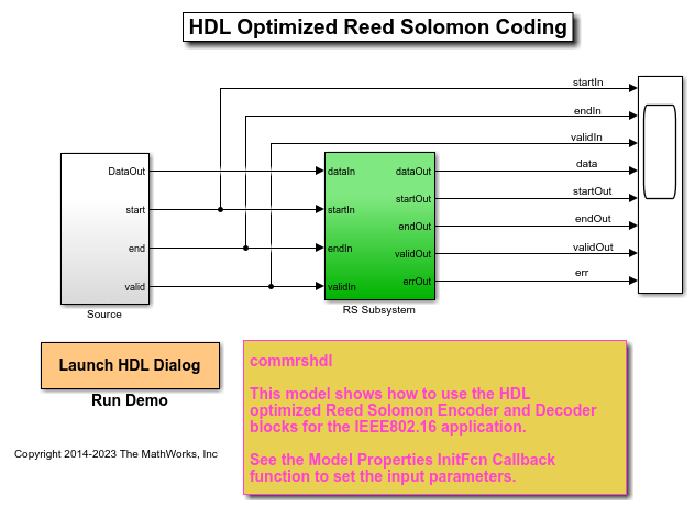
Source Subsystem
The Source subsystem generates the information symbols for the RS Encoder. To open the Source subsystem, run the following commands:
systemname = [modelname '/Source'];
open_system(systemname);
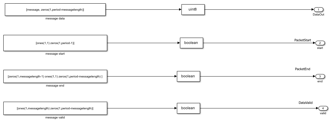
One of the messages (information symbols) employed by the IEEE 802.16 standard contains 36 bytes randomized data specified on page 827 of [ 1 ].
  message = [D4 BA A1 12 F2 74 96 30 27 D4 88 9C 96 E3 A9 52 B3 15 AB FD
  92 53 07 32 C0 62 48 F0 19 22 E0 91 62 1A C1 00].
The Source subsystem repeatedly transmits the message followed by a guard interval. The model has parameters messagelength for the number of symbols in the message to encode and period, which includes the messagelength and the guard interval length. The guard interval between messages accommodates the latency of the encoder adding parity check symbols to the message, and the decoder performing a Chien search. In the InitFcn callback of the model, the messagelength is set to 36 and period is set to 708, which indicates that the guard interval has a length of 672 symbols. To get the proper output for two sequential input messages, the guard interval between the messages must be greater than the sum of the block latency and the mask parameter Message length.
You can vary the messagelength and period values based on your requirements.
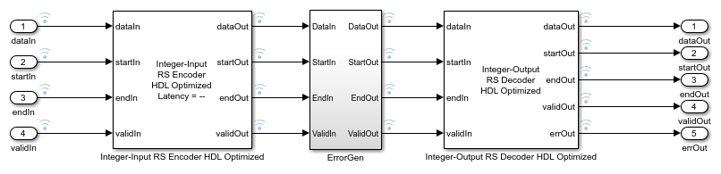
The top-level RS Subsystem contains the HDL Optimized RS Encoder and Decoder blocks. To open the RS Subsystem, run the following commands:
systemname = [modelname '/RS Subsystem'];
open_system(systemname);
The values of and are set in the InitFcn callback of the model and are used to configure the HDL Optimized RS Encoder and Decoder blocks. You cannot change the values of and in this model.
The RS encoder infers a shortened code if the message length is less than symbols. In this case, it pads the input message with  zeros, encodes the padded message, and appends 16 parity check symbols. The block then removes the added zeros symbols, creating a
  symbol output.
The field generator polynomial employed by IEEE 802.16 standard is  . Accordingly, for both RS encoder and decoder, the Source of primitive polynomial is set as
 Property, the Primitive polynomial is set to [1 0 0 0 1 1 1 0 1], the Source of B which is the starting power for roots of the primitive polynomial is set to Property, and the B value is set as 0. The code generator polynomial used by IEEE 802.16 standard is  , where
  .
.
Restrictions on  and the codeword length are detailed on the Integer-Input RS Encoder block reference page. The
 ErrorGen subsystem adds noise to the RS encoded message. To open the this subsystem, run the following commands:
systemname = [modelname '/RS Subsystem/ErrorGen'];
open_system(systemname);
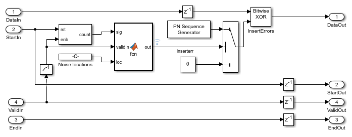
The ErrorGen subsystem implements the logic to add noise to the codewords at locations specified in the Noise Locations constant. The location can be changed as desired. In this example, the noise is added to the 5th, 23rd, 34th, and 12th codewords, corresponding to the symbols F2, 07, 1A, and 9C. The MATLAB® function block outputs logical true only at these four time instances for each packet, and activates a bitwise XOR operation between the original symbols and the noise.
Run Model
Run the model using the following command:
sim(modelname);
View Output
Use Logic Analyzer to view multiple signals in a window. Viewing signals in this way makes it easier to observe transitions. Signals in this model at various stages, namely, before encoding, after encoding, after adding noise, and after decoding are streamed. The blue icon in the model indicates streamed signals. Launch the Logic Analyzer from the model's toolstrip.

Analyze Results
In the Logic Analyzer output the inputdata signal represents the input of the RS encoder block and this is the 36 byte message given in the IEEE 802.16 specification. The encoded data shows the output of the RS encoder block. Note that the IEEE 802.16 specification performs puncturing of the parity bytes and retains only the first four bytes of the 16 bytes. In this example all 16 bytes of parity are used and the first four bytes of parity are 49, 31, 40, and BF, matching the IEEE 802.16 specification.
The errdata signal represents the encoded data with noise added in the specified noise locations. These noise locations are marked with 1s in the inserterr signal.
The decoded and corrected message out of the RS decoder block is shown by the outputdata signal. Note that the RS decoder block introduces about 3 period lengths of latency. Observe outputdata to see that the errors induced by noise are corrected.
Generate HDL Code and Test Bench
To check and generate HDL code for this example, you must have an HDL Coder™ license.
Get a unique temporary directory name for the generated files,
workingdir = tempname;
To check whether there are any issues with the model for HDL code generation, you can run the following command:
checkhdl('commrshdl/RS Subsystem','TargetDirectory',workingdir);Enter the following command to generate HDL code:
makehdl('commrshdl/RS Subsystem','TargetDirectory',workingdir);Enter the following command to generate the test bench:
makehdltb('commrshdl/RS Subsystem','TargetDirectory',workingdir);ModelSim Output
The following figure shows the ModelSim® HDL simulator after running the generated .do file scripts for the test bench. Compare the ModelSim result with the Simulink® result as shown below.

Selected References
1. IEEE 802.16: IEEE Standard for Air Interface for Broadband Wireless Access Systems(Revision of IEEE Std 802.16-2009). IEEE-SA. 8 June 2012.
2. George C. Clark Jr, J. Bibb Cain, Error-Correction Coding for Digital Communications, New York: Springer, 1981.
You can also select a web site from the following list:
Americas
- América Latina (Español)
- Canada (English)
- United States (English)
Europe
- Belgium (English)
- Denmark (English)
- Deutschland (Deutsch)
- España (Español)
- Finland (English)
- France (Français)
- Ireland (English)
- Italia (Italiano)
- Luxembourg (English)
- Netherlands (English)
- Norway (English)
- Österreich (Deutsch)
- Portugal (English)
- Sweden (English)
- Switzerland
- United Kingdom (English)