Comb Filter
(To be removed) Design comb Filter
The Comb Filter block will be removed in a future release. Use the Discrete FIR Filter (Simulink) block or the Second-Order Section Filter block instead.
Library
Filtering / Filter Designs
dspfdesign
Description
This block brings the filter design capabilities of the filterBuilder function to the Simulink® environment.
Dialog Box
See Comb Filter Design —Main Pane for more information about the parameters of this block. The Data Types and Code Generation panes are not available for blocks in the DSP System Toolbox™ Filter Designs library.
- View filter response
This button opens the Filter Visualization Tool (FVTool) from the Signal Processing Toolbox™ product. You can use the tool to display:
Magnitude response, phase response, and group delay in the frequency domain.
Impulse response and step response in the time domain.
Pole-zero information.
The tool also helps you evaluate filter performance by providing information about filter order, stability, and phase linearity. For more information on FVTool, see the Signal Processing Toolbox documentation.
Filter Specifications
In this group, you specify the type of comb filter and the number of peaks or notches.
- Comb Type
Select either
NotchorPeakfrom the drop-down list.Notchcreates a comb filter that attenuates a set of harmonically related frequencies.Peakcreates a comb filter that amplifies a set of harmonically related frequencies.- Order mode
Select either
OrderorNumber of Peaks/Notchesfrom the drop-down menu.Select
Orderto enter the desired filter order in the dialog box. The comb filter has notches or peaks at increments of 2/Orderin normalized frequency units.Select
Number of PeaksorNumber of Notchesto specify the number of peaks or notches and theShelving filter order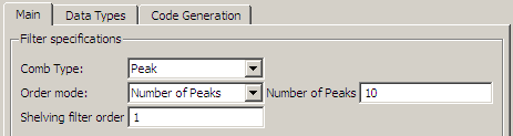 .
.- Shelving filter order
The
Shelving filter orderis a positive integer that determines the sharpness of the peaks or notches. Larger values result in sharper peaks or notches.
Frequency specifications
In this group, you specify the frequency constraints and frequency units.
- Frequency specifications
Select either
Quality factororBandwidth.Quality factoris the ratio of the center frequency of the peak or notch to the bandwidth calculated at the –3 dB point.Bandwidthspecifies the bandwidth of the peak or notch. By default the bandwidth is measured at the –3 dB point. For example, setting the bandwidth equal to 0.1 results in 3 dB frequencies at normalized frequencies 0.05 above and below the center frequency of the peak or notch.- Frequency Units
Specify the frequency units. The default is normalized frequency. Choosing an option in Hz enables the Input sample rate dialog box.
Magnitude specifications
Specify the units for the magnitude specification and the gain at which the bandwidth is measured. This menu is disabled if you specify a filter order. Select one of the following magnitude units from the drop down list:
dB— Specify the magnitude in decibels (default).Squared— Specify the magnitude in squared units.
Bandwidth gain — Specify the gain at which the bandwidth is measured. The default is –3 dB.
Algorithm
The parameters in this group allow you to specify the design method and structure of your filter.
- Design Method
The IIR Butterworth design is the only option for peaking or notching comb filters.
Filter Implementation
- Structure
For the filter specifications and design method you select, this parameter lists the filter structures available to implement your filter.
- Use basic elements to enable filter customization
Select this check box to implement the filter as a subsystem of basic Simulink blocks. Clear the check box to implement the filter as a high-level subsystem. By default, this check box is cleared.
The high-level implementation provides better compatibility across various filter structures, especially filters that would contain algebraic loops when constructed using basic elements. On the other hand, using basic elements enables the following optimization parameters:
Optimize for zero gains — Terminate chains that contain Gain blocks with a gain of zero.
Optimize for unit gains — Remove Gain blocks that scale by a factor of one.
Optimize for delay chains — Substitute delay chains made up of n unit delays with a single delay by n.
Optimize for negative gains — Use subtraction in Sum blocks instead of negative gains in Gain blocks.
- Optimize for unit-scale values
Select this check box to scale unit gains between sections in SOS filters. This parameter is available only for SOS filters.
- Input processing
Specify how the block should process the input. The available options may vary depending on he settings of the Filter Structure and Use basic elements for filter customization parameters. You can set this parameter to one of the following options:
Columns as channels (frame based)— When you select this option, the block treats each column of the input as a separate channel.Elements as channels (sample based)— When you select this option, the block treats each element of the input as a separate channel.
- Rate options
When the Filter type parameter specifies a multirate filter, select the rate processing rule for the block from following options:
Enforce single-rate
                                                  processing
— When you select this option, the block maintains the sample rate of the input.Allow multirate processing— When you select this option, the block adjusts the rate at the output to accommodate an increased or reduced number of samples. To select this option, you must set the Input processing parameter toElements as channels (sample based).
- Use variable names for coefficients
Select this check box to enable the specification of coefficients using MATLAB® variables. The available coefficient names differ depending on the filter structure. Using symbolic names allows tuning of filter coefficients in generated code. By default, this check box is cleared.
Supported Data Types
| Port | Supported Data Types |
|---|---|
Input |
|
Output |
|
Extended Capabilities
Version History
Introduced in R2010aYou can also select a web site from the following list:
Americas
- América Latina (Español)
- Canada (English)
- United States (English)
Europe
- Belgium (English)
- Denmark (English)
- Deutschland (Deutsch)
- España (Español)
- Finland (English)
- France (Français)
- Ireland (English)
- Italia (Italiano)
- Luxembourg (English)
- Netherlands (English)
- Norway (English)
- Österreich (Deutsch)
- Portugal (English)
- Sweden (English)
- Switzerland
- United Kingdom (English)