Main Content

iirlp2mb

Transform IIR lowpass filter to IIR multiband filter

Description

example

[num,den,allpassNum,allpassDen] = iirlp2mb(b,a,wo,wt) transforms an IIR lowpass filter to an IIR multiband filter.

The iirlp2mb function returns the numerator and denominator coefficients of the transformed IIR multiband filter. The function also returns the numerator, allpassNum, and the denominator, allpassDen, of the Mth order allpass mapping filter. The prototype lowpass filter is specified with the numerator b and the denominator a.

The function transforms a real lowpass prototype filter to a multiband filter by applying an Mth-order real lowpass to real multiple bandpass frequency mapping. Parameter M is the number of times an original feature is replicated in the transformed filter. By default the DC feature is kept at its original location. For more details, see IIR Lowpass Filter to IIR Multiband Filter Transformation.

[num,den,allpassNum,allpassDen] = iirlp2mb(b,a,wo,wt,pass) allows you to specify an additional parameter, pass as 'pass' or 'stop', which chooses between using the “Nyquist Mobility” and the “DC Mobility”, respectively. In the case of “Nyquist Mobility”, the DC feature is kept at an original frequency and the Nyquist feature is free to move. In the case of “DC Mobility”, the Nyquist feature stays at its original location and the DC feature is free to move.

Frequencies must be normalized to be between 0 and 1, with 1 corresponding to half the sample rate.

Examples

collapse all

Transform a lowpass IIR filter to a multiband IIR filter using the iirlp2mb function.

Input Lowpass IIR Filter

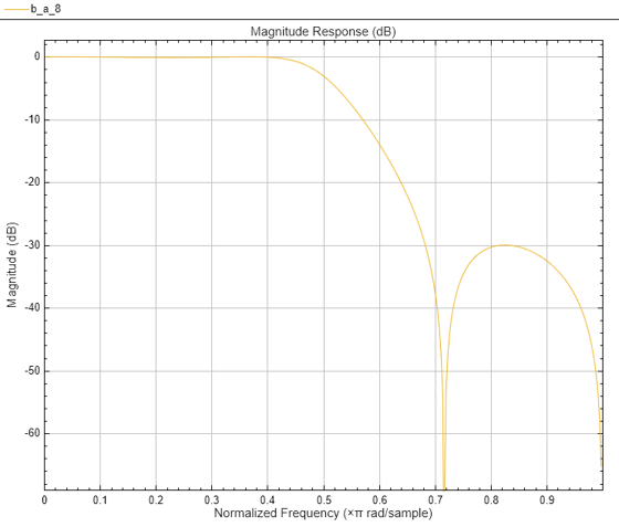
Design a prototype real IIR lowpass elliptic filter with a gain of about –3 dB at 0.5π rad/sample.

[b,a] = ellip(3,0.1,30,0.409);
fvtool(b,a)

Figure Figure 1: Magnitude Response (dB) contains an axes object. The axes object with title Magnitude Response (dB), xlabel Normalized Frequency ( times pi blank rad/sample), ylabel Magnitude (dB) contains an object of type line.

Transform Filter Using iirlp2mb

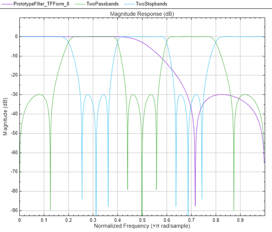
Transform the real prototype lowpass filter into a real multiband filter with two passbands.

Specify the prototype filter as a vector of numerator and denominator coefficients, b and a respectively.

[num1,den1] = iirlp2mb(b,a,0.5,[2 4 6 8]/10);

Transform the prototype filter into a real multiband filter with two stopbands.

Specify the prototype filter as a vector of numerator and denominator coefficients, b and a respectively.

[num2,den2] = iirlp2mb(b,a,0.5,[2 4 6 8]/10,"stop");

Compare the magnitude response of the filters using FVTool.

hvft = fvtool(b,a,num1,den1,num2,den2);
legend(hvft,"Prototype Filter (TF Form)",...
    "Two passbands","Two stopbands")

Figure Figure 2: Magnitude Response (dB) contains an axes object. The axes object with title Magnitude Response (dB), xlabel Normalized Frequency ( times pi blank rad/sample), ylabel Magnitude (dB) contains 3 objects of type line. These objects represent Prototype Filter (TF Form), Two passbands, Two stopbands.

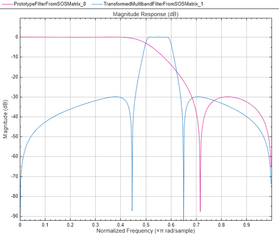
You can also specify the input lowpass IIR filter as a matrix of coefficients. Pass the second-order section matrices as inputs. Change the desired frequency locations to be [0.5 0.6] in normalized frequency units. The transformed 2-band filter is a fourth-order section filter given by the numerator and the denominator coefficients num3 and den3.

ss = tf2sos(b,a);
[num3, den3] = iirlp2mb(ss(:,1:3), ss(:,4:6),...
    0.5,[5 6]/10);

Compare the magnitude response of the filters using FVTool.

To visualize the magnitude response of the fourth-order section filter, first pass the filter coefficients to the dsp.FourthOrderSectionFilter object. Then, use this object as an input to the FVTool.

fos = dsp.FourthOrderSectionFilter(Numerator=num3,...
             Denominator=den3);
hvft = fvtool(ss,fos);
legend(hvft,"Prototype Filter (SOS Form)",...
    "Transformed Multiband Filter")

Figure Figure 3: Magnitude Response (dB) contains an axes object. The axes object with title Magnitude Response (dB), xlabel Normalized Frequency ( times pi blank rad/sample), ylabel Magnitude (dB) contains 2 objects of type line. These objects represent Prototype Filter (SOS Form), Transformed Multiband Filter.

Copyright 2012–2023 The MathWorks, Inc.

Input Arguments

collapse all

Numerator coefficients of the prototype lowpass IIR filter, specified as either:

  • Row vector –– Specifies the values of [b0, b1, …, bn], given this transfer function form:

    H(z)=B(z)A(z)=b0+b1z1++bnzna0+a1z1++anzn,

    where n is the order of the filter.

  • Matrix –– Specifies the numerator coefficients in the form of an P-by-(Q+1) matrix, where P is the number of filter sections and Q is the order of each filter section. If Q = 2, the filter is a second-order section filter. For higher-order sections, make Q > 2.

    b=[b01b11b21...bQ1b02b12b22...bQ2b0Pb1Pb2PbQP]

    In the transfer function form, the numerator coefficient matrix bik of the IIR filter can be represented using the following equation:

    H(z)=k=1PHk(z)=k=1Pb0k+b1kz1+b2kz2++bQkzQa0k+a1kz1+a2kz2++aQkzQ,

    where,

    • a –– Denominator coefficients matrix. For more information on how to specify this matrix, see a.

    • k –– Row index.

    • i –– Column index.

    When specified in the matrix form, b and a matrices must have the same number of rows (filter sections) Q.

Data Types: single | double
Complex Number Support: Yes

Denominator coefficients for a prototype lowpass IIR filter, specified as one of these options:

  • Row vector –– Specifies the values of [a0, a1, …, an], given this transfer function form:

    H(z)=B(z)A(z)=b0+b1z1++bnzna0+a1z1++anzn,

    where n is the order of the filter.

  • Matrix –– Specifies the denominator coefficients in the form of an P-by-(Q+1) matrix, where P is the number of filter sections and Q is the order of each filter section. If Q = 2, the filter is a second-order section filter. For higher-order sections, make Q > 2.

    a=[a01a11a21aQ1a02a12a22aQ2a0Pa1Pa2PaQP]

    In the transfer function form, the denominator coefficient matrix aik of the IIR filter can be represented using the following equation:

    H(z)=k=1PHk(z)=k=1Pb0k+b1kz1+b2kz2++bQkzQa0k+a1kz1+a2kz2++aQkzQ,

    where,

    • b –– Numerator coefficients matrix. For more information on how to specify this matrix, see b.

    • k –– Row index.

    • i –– Column index.

    When specified in the matrix form, a and b matrices must have the same number of rows (filter sections) P.

Data Types: single | double
Complex Number Support: Yes

Frequency value to transform from the prototype filter, specified as a real scalar. Frequency wo must be normalized to be between 0 and 1, with 1 corresponding to half the sample rate.

Data Types: single | double

Desired frequency locations in the transformed target filter, specified as a row vector. Frequencies in wt must be normalized to be between 0 and 1, with 1 corresponding to half the sample rate. The value of M which is equal to the number of times an original feature is replicated in the transformed filter equals the length of the wt vector.

Data Types: single | double

Choice of passband or stopband at DC, specified as either:

  • "pass" –– “Nyquist Mobility”. The DC feature is kept at an original frequency and the Nyquist feature is free to move.

  • "stop" –– “DC Mobility”. The Nyquist feature stays at its original location and the DC feature is free to move.

Output Arguments

collapse all

Numerator coefficients of the transformed multiband filter, returned as one of the following:

  • Row vector of length Mn+1, where M is the number of times an original feature is replicated in the transformed filter and n is the order of the input filter. The value of M equals the length of the wt vector.

    The num output is a row vector when the input coefficients b and a are row vectors.

  • P-by-(QM+1) matrix, where P is the number of filter sections, Q is the order of each section of the transformed filter, and M is the number of times an original feature is replicated in the transformed filter.

    The num output is a matrix when the input coefficients b and a are matrices.

Data Types: single | double
Complex Number Support: Yes

Denominator coefficients of the transformed multiband filter, returned as one of the following:

  • Row vector of length Mn+1, where M is the number of times an original feature is replicated in the transformed filter and n is the order of the input filter. The value of M equals the length of the wt vector.

    The den output is a row vector when the input coefficients b and a are row vectors.

  • P-by-(QM+1) matrix, where P is the number of filter sections, Q is the order of each section of the transformed filter, and M is the number of times an original feature is replicated in the transformed filter.

    The den output is a matrix when the input coefficients b and a are matrices.

Data Types: single | double
Complex Number Support: Yes

Numerator coefficients of the mapping filter, returned as a row vector.

Data Types: single | double

Denominator coefficients of the mapping filter, returned as a row vector.

Data Types: single | double

More About

collapse all

IIR Lowpass Filter to IIR Multiband Filter Transformation

IIR lowpass filter to IIR multiband filter transformation effectively places one feature of the original filter, located at frequency wo, at the required target frequency locations, wt1, … ,wtM.

Relative positions of other features of the original filter do not change in the target filter. It is possible to select two features of an original filter, F1 and F2, with F1 preceding F2. Feature F1 will still precede F2 after the transformation. However, the distance between F1 and F2 will not be the same before and after the transformation.

Choice of the feature subject to this transformation is not restricted to the cutoff frequency of an original lowpass filter. You can choose to transform any feature of the original filter like stopband edge, DC, deep minimum in the stopband, or others.

The IIR lowpass filter to IIR multiband filter transformation can also be used to transform other types of filters, for example, notch filters or resonators can be easily replicated at a number of required frequency locations without redesigning them. A good application would be an adaptive tone cancellation circuit reacting to the changing number and location of tones.

References

[1] Franchitti, Jean-Claude. “All-pass filter interpolation and frequency transformation problems.” MSc Thesis, Dept. of Electrical and Computer Engineering, University of Colorado, 1985.

[2] Feyh, G., J.C. Franchitti and C.T. Mullis.“All-pass filter interpolation and frequency transformation problem.” Proceedings 20th Asilomar Conference on Signals, Systems and Computers, Pacific Grove, California, pp. 164-168, November 1986.

[3] Mullis, C.T. and R. A. Roberts. Digital Signal Processing, section 6.7, Reading, Mass., Addison-Wesley, 1987.

[4] Feyh, G., W.B. Jones and C.T. Mullis. “An extension of the Schur Algorithm for frequency transformations.” Linear Circuits, Systems and Signal Processing: Theory and Application. C. J. Byrnes et al Eds, Amsterdam: Elsevier, 1988.

Extended Capabilities

C/C++ Code Generation
Generate C and C++ code using MATLAB® Coder™.

Version History

Introduced in R2011a
See Also

Functions