azel2phithetapat
Convert radiation pattern from azimuth-elevation coordinates to phi-theta coordinates
Syntax
Description
pat_phitheta = azel2phithetapat(pat_azel,az,el)pat_azel, from azimuth and
elevation coordinates to the pattern, pat_phitheta, in phi and theta
coordinates. az and el are the azimuth and
elevation angles at which the pat_azel values are defined. The
pat_phitheta matrix covers theta values from 0 to 180 degrees and phi
values from 0 to 360 degrees in one degree increments. The function interpolates the
pat_azel matrix to estimate the response of the antenna in a given
phi-theta direction.
pat_phitheta = azel2phithetapat(___,'RotateZ2X',rotpatax)rotpatax to indicate the boresight direction of the
pattern along the x-axis or the z-axis.
[
also returns vectors pat_phitheta,phi_pat,theta_pat] = azel2phithetapat(___)phi_pat and theta_pat
containing the phi and theta angles at which pat_phitheta is
sampled.
Examples
Convert Radiation Pattern to Phi-Theta
Convert a radiation pattern to φ/θ form, with the φ and θ angles spaced 1 degree apart.
Define the pattern in terms of azimuth and elevation.
az = -180:180;
el = -90:90;
pat_azel = mag2db(repmat(cosd(el)',1,numel(az)));
Convert the pattern to φ/θ space.
pat_phitheta = azel2phithetapat(pat_azel,az,el);
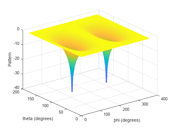
Plot Converted Radiation Pattern
Plot the result of converting a radiation pattern to space with the and angles spaced 1 degree apart.
The radiation pattern is the cosine of the elevation.
az = -180:180;
el = -90:90;
pat_azel = repmat(cosd(el)',1,numel(az));
Convert the pattern to space. Use the returned and angles for plotting.
[pat_phitheta,phi,theta] = azel2phithetapat(pat_azel,az,el);
Plot the result.
H = surf(phi,theta,mag2db(pat_phitheta));
H.LineStyle = 'none';
xlabel('phi (degrees)');
ylabel('theta (degrees)');
zlabel('Pattern');
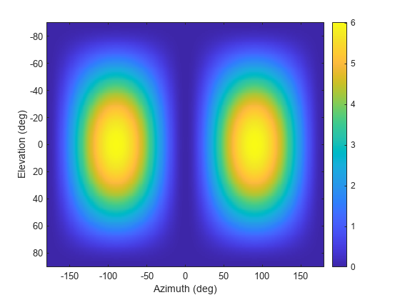
Convert Radiation Pattern to Alternate Phi-Theta Coordinates
Convert a radiation pattern to the alternate phi-theta coordinates, with the phi and theta angles spaced one degree apart.
Create a simple radiation pattern in terms of azimuth and elevation. Add an offset to the pattern to suppress taking the logarithm of zero in mag2db.
az = -180:180;
el = -90:90;
pat_azel = mag2db(cosd(el).^2'*sind(az).^2 + 1);

imagesc(az,el,pat_azel)
xlabel('Azimuth (deg)')
ylabel('Elevation (deg)')
colorbar
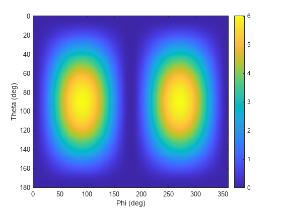
Convert the pattern to phi-theta space.
[pat_phitheta,phi_pat,theta_pat] = azel2phithetapat(pat_azel,az,el,'RotateZ2X',false);
imagesc(phi_pat,theta_pat,pat_phitheta)
xlabel('Phi (deg)')
ylabel('Theta (deg)')
colorbar
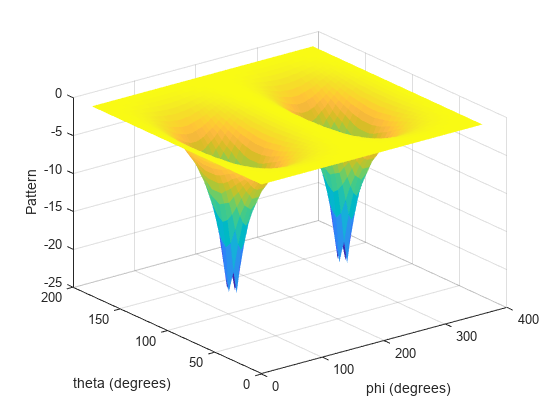
Convert Radiation Pattern for Specific Phi/Theta Values
Convert a radiation pattern to space with and angles spaced 5 degrees apart.
The radiation pattern is the cosine of the elevation.
az = -180:180;
el = -90:90;
pat_azel = repmat(cosd(el)',1,numel(az));
Define the set of and angles at which to sample the pattern. Then, convert the pattern.
phi = 0:5:360;
theta = 0:5:180;
pat_phitheta = azel2phithetapat(pat_azel,az,el,phi,theta);
Plot the result.
H = surf(phi,theta,mag2db(pat_phitheta));
H.LineStyle = 'none';
xlabel('phi (degrees)');
ylabel('theta (degrees)');
zlabel('Pattern');
Input Arguments
Output Arguments
More About
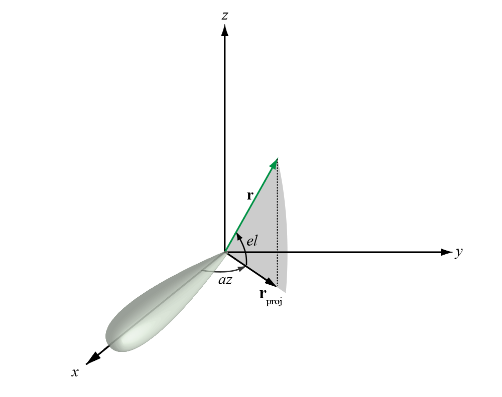
Azimuth and Elevation Angles
The azimuth angle of a vector is the angle between the x-axis and the orthogonal projection of the vector onto the xy plane. The angle is positive in going from the x axis toward the y axis. Azimuth angles lie between –180 and 180 degrees. The elevation angle is the angle between the vector and its orthogonal projection onto the xy-plane. The angle is positive when going toward the positive z-axis from the xy plane. By default, the boresight direction of an element or array is aligned with the positive x-axis. The boresight direction is the direction of the main lobe of an element or array.
Note
The elevation angle is sometimes defined in the literature as the angle a vector makes with the positive z-axis. The MATLAB® and Phased Array System Toolbox™ products do not use this definition.
This figure illustrates the azimuth angle and elevation angle for a vector shown as a green solid line.
Phi and Theta Angles
The phi angle (φ) is the angle from the positive y-axis to the vector’s orthogonal projection onto the yz plane. The angle is positive toward the positive z-axis. The phi angle is between 0 and 360 degrees. The theta angle (θ) is the angle from the x-axis to the vector itself. The angle is positive toward the yz plane. The theta angle is between 0 and 180 degrees.
The figure illustrates phi and theta for a vector that appears as a green solid line.
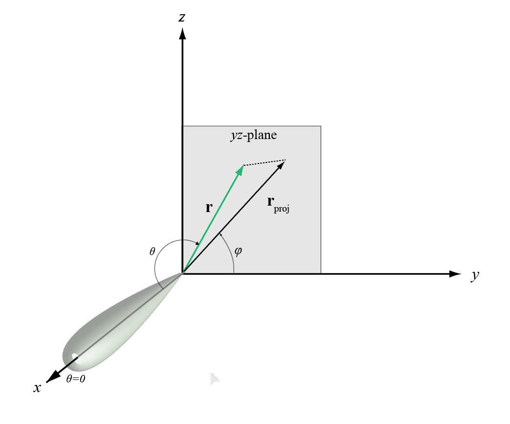
The coordinate transformations between φ/θ and az/el are described by the following equations
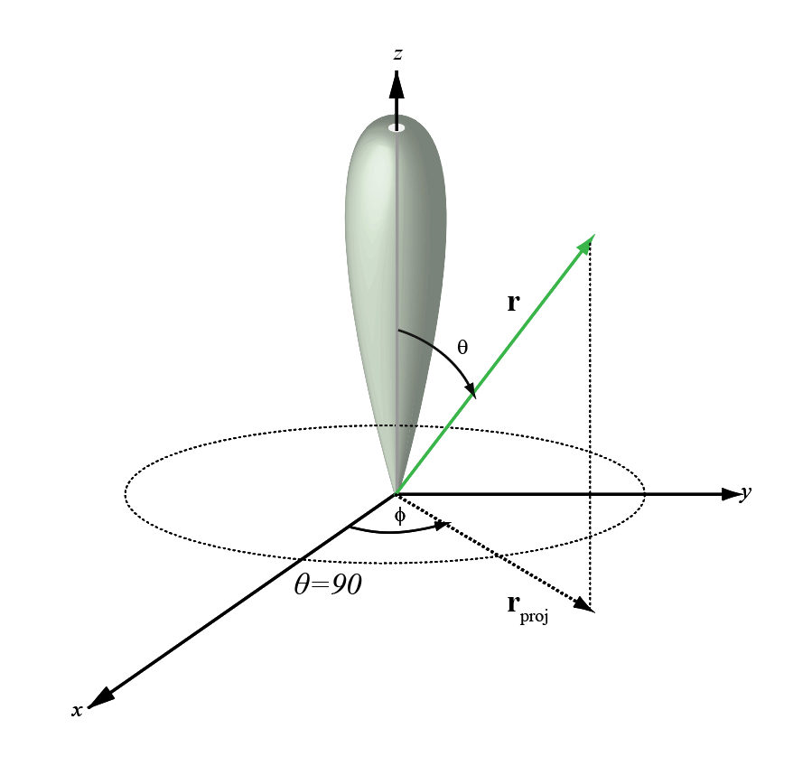
Alternative Definition of Phi and Theta
The phi angle (φ) is the angle from the positive x-axis to the vector’s orthogonal projection onto the xy plane. The angle is positive toward the positive y-axis. The phi angle is between 0 and 360 degrees. The theta angle (θ) is the angle from the z-axis to the vector itself. The angle is positive toward the xy plane. The theta angle is between 0 and 180 degrees.
The figure illustrates φ and θ for a vector that appears as a green solid line.
Extended Capabilities
Version History
Introduced in R2012a
You can also select a web site from the following list:
Americas
- América Latina (Español)
- Canada (English)
- United States (English)
Europe
- Belgium (English)
- Denmark (English)
- Deutschland (Deutsch)
- España (Español)
- Finland (English)
- France (Français)
- Ireland (English)
- Italia (Italiano)
- Luxembourg (English)
- Netherlands (English)
- Norway (English)
- Österreich (Deutsch)
- Portugal (English)
- Sweden (English)
- Switzerland
- United Kingdom (English)