Run Executables for Variant Blocks Without Recompiling Code for Changing Active Choices
This example explains how to generate code for multiple implementations of a component represented using a Variant Subsystem block. The different variations, referred to as variant choices, are guarded by if and else if conditional statements in the generated code. These conditional statements enable conditional execution, selectively including or excluding code based on the variant condition that evaluates to true during code execution. By including multiple variant choices, you are not required to recompile code each time the value of the variant control variable changes. This approach also allows for analyzing variant choices for potential incompatibilities, such as data type and dimension mismatches, prior to simulation and code generation.
Prerequisites
To learn more about how to use Variant Source and Variant Sink blocks in Simulink®, see Propagate Variant Conditions to Define Variant Regions Using Variant Source and Variant Sink Blocks.
To get started with variant code generation, see Generate Code for Variant Source and Variant Sink Blocks.
Represent Variant Choices in Variant Source and Variant Sink Blocks
The slexVariantSourceAndSink model contains two Variant Source blocks, Variant Source1 and Variant Source2, and a Variant Sink block. The variant conditions at the input ports and the output ports of the Variant Source and the Variant Sink blocks determine the activation and deactivation of the blocks connected to them.
model = "slexVariantSourceAndSink";
open_system(model);

Specify Variant Controls for Variant Choice Selection
Each variant choice in the model is associated with a variant control. Variant controls determine which variant choice is active. By changing the value of a variant control, you can switch the active variant choice. While each variant choice is associated with a variant control, only one variant control can evaluate to true. When a variant control evaluates to true, Simulink activates the variant choice that corresponds to that variant control. For more information, see Introduction to Variant Controls.
1. Right-click the variant badge on the variant blocks and select Block Parameters. In this example, each variant choice in the variant blocks is associated with variant control variables V and W. The variables V and W are Simulink.ParameterV and W are set to ExportedGlobal to generate global variable definitions and declarations for both V and W in the generated code.
V = Simulink.Parameter;
V.Value = 1;
V.DataType = "int32";
V.CoderInfo.StorageClass = "ExportedGlobal";
W = Simulink.Parameter;
W.Value = 1;
W.DataType = "int32";
W.CoderInfo.StorageClass = "ExportedGlobal";
You can access the values of V and W using #include statements in your external code. You must specify the source file of your external code in Model Settings > Code Generation > Custom Code > Code information > Source files. In this example, the ReadVarControl.c file sets the values of V and W to 2, as shown. You can modify the code to read the values of V and W from a sensor or a hardware, if required.
configSet = getActiveConfigSet(gcs);
set_param(configSet,CustomSource="ReadVarControl.c")
set_param(configSet,CustomHeaderCode="ReadVarControl.h")
// ReadVarControl.c
#include "rtwtypes.h"
extern int32_T V;
extern int32_T W;
void SetValueOfVarControls()
{
   // The values of V and W can be read from a sensor or hardware
   // for simplicity it is hardcoded.
   V = 2;
   W = 2;
}
For the list of storage classes supported for the Simulink.Parameter type of variant control variables, see Storage Classes for Different Variant Activation Times.
2. In the MATLAB™ Command Window, set the value of V to 1 and W to 1. Simulate the model. During simulation, the variant conditions V == 1 and W == 1 evaluate to true, activating the first input ports of the Variant Source2 and Variant Sink blocks.
V.Value = 1;
W.Value = 1;
sim(model);
3. Set the value of V to 2 and W to 1. Simulate the model again. During simulation, the variant conditions V == 2 and W == 1 evaluate to true, activating the first input port of the Variant Source1 block and the second input port of the Variant Source2 block.
V.Value = 2;
W.Value = 1;
sim(model);
For information on the variant conditions that activate the Variant Source1 and the Variant Sink blocks, see Propagate Variant Conditions to Define Variant Regions Using Variant Source and Variant Sink Blocks.
This mechanism allows you to swap the active and inactive choices to the variant blocks without modifying the model structure, making the model flexible and adaptable to different scenarios.
If the Simulink.Parameter objects are not suitable for your requirements, you can use different types of variant controls as described in Compare Different Types of Variant Control Modes in Variant Blocks.
Configure Model to Generate Code with if Conditional Statements
By default, Simulink supports generating code only for a specific choice of a variant block. You can customize your model to generate code for multiple variant choices of the block using the Variant activation time parameter. Using the Variant activation time parameter enables you to set the active variant choice at different stages of simulation and code generation. This can improve the speed of simulation and allow you to reuse the artifacts from previous runs in code generation. It also enables you to analyze variant choices for incompatibilities, such as data type and dimension mismatches, prior to simulation and code generation. For more information, see Activate Variant During Different Stages of Simulation and Code Generation Workflow.
To generate code for all the variant choices of the variant blocks guarded by if and else if conditional statements, ensure that the Variant activation time parameter of the blocks are set to startup.
set_param(model+"/Variant Source1","VariantActivationTime","startup");
set_param(model+"/Variant Source2","VariantActivationTime","startup");
set_param(model+"/Variant Sink","VariantActivationTime","startup");
1. In the Apps tab of the toolstrip, navigate to Simulink Coder or Embedded Coder.
2. In the C code tab, select Build > Generate code. Observe that the generated code includes the logic for all the variant choice blocks.
For detailed information on settings to generate code, see Generate Code Using Simulink Coder.
slbuild(model);
### Starting build procedure for: slexVariantSourceAndSink
### Successful completion of build procedure for: slexVariantSourceAndSink

Build Summary

Top model targets built:

Model                     Action                        Rebuild Reason
==========================================================================================================
slexVariantSourceAndSink  Code generated and compiled.  Code generation information file does not exist.

1 of 1 models built (0 models already up to date)
Build duration: 0h 0m 13.46s
Review Generated Code
1. In the C Code tab of the toolstrip, select Open Report.
2. Locate and select the slexVariantSourceAndSink.h file from the left pane. This file defines variant controls as global variables (extern) to access the value of V and W from an external source ReadVarControl.c.
extern int32_T V;         /* Variable: V
                          * Referenced by:
                          *   '<Root>/Out1'
                          *   '<Root>/Gain3'
                          *   '<Root>/Sine1'
                          *   '<Root>/Sine2'
                          *   '<Root>/Sine4'
                          *   '<Root>/Add1'
                          *   '<Root>/V'
                          */
extern int32_T W;         /* Variable: W
                          * Referenced by:
                          *   '<Root>/Out3'
                          *   '<Root>/Out4'
                          *   '<Root>/Gain4'
                          *   '<Root>/Gain5'
                          *   '<Root>/Sine5'
                          *   '<Root>/Sum'
                          *   '<Root>/W'
                          */
Observe the use of #include in your external code ReadVarControl.c to set the values of V and W to 2.
/* Copyright 2021 The MathWorks, Inc. */
#include "rtwtypes.h"
extern int32_T V;
extern int32_T W;
void SetValueOfVarControls()
{
    // The values of V and W can be read from a sensor or hardware
    // for simplicity it is hardcoded.
    V = 2;
    W = 2;
}
3. Locate and select the slexVariantSourceAndSink.c file from the left pane.
In the generated code:
The definition of the
slexVariantSourceAndSink_stepfunction contains all the variant choices. The variant choices are guarded byifandelse ifconditional statements. Simulink evaluates the conditions and executes the compiled code only for the active variant choices of the variant blocks. You can then specify a different value forVandWin theReadVarControl.cfile, and then recompile the same code for any other variant choices of the variant blocks.
/* Model step function */
void slexVariantSourceAndSink_step(void)
{
 ...
 if (V == 1) {
   rtb_Sine6 = sin(((real_T)slexVariantSourceAndSink_DW.counter +
                    slexVariantSourceAndSink_P.Sine1_Offset) * 2.0 *
                   3.1415926535897931 /
                   slexVariantSourceAndSink_P.Sine1_NumSamp) *
     slexVariantSourceAndSink_P.Sine1_Amp +
     slexVariantSourceAndSink_P.Sine1_Bias;
  } else if (V == 2) {
   /* Sin: '<Root>/Sine2' */
   rtb_Gain5 = sin(((real_T)slexVariantSourceAndSink_DW.counter_i +
                    slexVariantSourceAndSink_P.Sine2_Offset) * 2.0 *
                   3.1415926535897931 /
                   slexVariantSourceAndSink_P.Sine2_NumSamp) *
     slexVariantSourceAndSink_P.Sine2_Amp +
     slexVariantSourceAndSink_P.Sine2_Bias;
 }
if ((V == 2) && (W == 1)) {
  slexVariantSourceAndSink_B.VariantMerge_For_Variant_Source = sin(((real_T)
    slexVariantSourceAndSink_DW.counter_f +
    slexVariantSourceAndSink_P.Sine3_Offset) * 2.0 * 3.1415926535897931 /
    slexVariantSourceAndSink_P.Sine3_NumSamp) *
    slexVariantSourceAndSink_P.Sine3_Amp +
    slexVariantSourceAndSink_P.Sine3_Bias;
}
if (V == 2) {
  rtb_Sine6 = rtb_Gain5 +
    slexVariantSourceAndSink_B.VariantMerge_For_Variant_Source;
}
if ((V == 1) || (V == 2)) {
  slexVariantSourceAndSink_Y.Out1 = slexVariantSourceAndSink_P.Gain3_Gain *
    rtb_Sine6;
}
if (W == 1) {
  rtb_Gain5 = slexVariantSourceAndSink_P.Gain4_Gain * rtb_Gain5 *
    slexVariantSourceAndSink_P.Gain5_Gain;
  rtb_VM_Conditional_Signal_Sum_1 = rtb_Gain5;
} else {
  /* SignalConversion generated from: '<Root>/Sum' */
  rtb_VM_Conditional_Signal_Sum_1 = 0.0;
}
...
if (W == 1) {
  slexVariantSourceAndSink_Y.Out3 = rtb_Gain5;
}
if (V == 1) {
  slexVariantSourceAndSink_DW.counter++;
  if (slexVariantSourceAndSink_DW.counter ==
      slexVariantSourceAndSink_P.Sine1_NumSamp) {
    slexVariantSourceAndSink_DW.counter = 0;
  }
} else if (V == 2) {
  /* Update for Sin: '<Root>/Sine2' */
  slexVariantSourceAndSink_DW.counter_i++;
  if (slexVariantSourceAndSink_DW.counter_i ==
      slexVariantSourceAndSink_P.Sine2_NumSamp) {
    slexVariantSourceAndSink_DW.counter_i = 0;
  }
}
if ((V == 2) && (W == 1)) {
  slexVariantSourceAndSink_DW.counter_f++;
  if (slexVariantSourceAndSink_DW.counter_f ==
      slexVariantSourceAndSink_P.Sine3_NumSamp) {
    slexVariantSourceAndSink_DW.counter_f = 0;
  }
}
...
}
The block variables in the
initializefunction are not guarded in conditional statements. The variables are set up every time you compile the code, regardless of the active variant blocks. This prevents the execution of the code with incorrect or unintended values due to a variant condition not being met. In other words, unguarded code avoids the situation where the initialization might be skipped, which could lead to unpredictable results.
The parameters used as variant control variables for
startupactivation do not appear in the generated C API (C Application Programming Interface) or ASAP2 (ASAM MCD-2 MC) interfaces because the startup conditions are evaluated at compile time to determine the active variant. They are not present at run time. Therefore, they have no representation in the interfaces, which are used for run-time activities such as calibration.
The values of variant control variables within the
initializefunction can be modified. Avoid making changes to these values within theslexVariantSourceAndSink_stepfunction using a custom code, as the generated code may not be designed to effectively manage the transition between different variants. While you can include a check in the generated code to prevent modifications to variant control values within theslexVariantSourceAndSink_stepfunction, this additional check may impact the performance of the resulting generated code. In this example, theslexVariantSourceAndSink_initializefunction calls theSetValueOfVarControlsfunction to set the values ofVandW. TheSetValueOfVarControlsfunction is defined in theReadControlVar.cfile.
void slexVariantSourceAndSink_initialize(void)
{
  ...
 SetValueOfVarControls();
 slexVaria_startupVariantChecker();
}
// ReadVarControl.c
#include "rtwtypes.h"
extern int32_T V;
extern int32_T W;
void SetValueOfVarControls()
{
// The values of V and W can be read from a sensor or hardware
// for simplicity it is hardcoded.
V = 2;
W = 2;
}The
utAssertstatements in theinitializefunction make sure that the generated code behavior for variant blocks matches the simulation. In this example, the Allow zero active variant control parameter is selected. The statementutAssert((V == 1) + (V == 2) <= 1)enforces the rule that no more than one variant can be active for theVariant Source2block. If you do not select the Allow zero active variant control parameter, theutAssertstatement makes sure that at least one variant is active.
To generate code that includes logic for active and inactive choices, allowing for conditional compilation based on specific choices, see Compile Code Conditionally for Variations of Component Represented Using Variant Block.
Startup Variants with Continuous State Blocks
This example shows you how to simulate and generate code for variant choices of startup variant blocks comprising of continuous state blocks. In the generated code, the derivatives of the all the continuous blocks are set to zero and then assigned appropriate values in regular if statements.
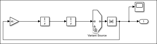
Consider this model containing a Variant Source block with the startup activation time. The model contains the continuous blocks Integ1 with its Initial condition set to 0 and Integ2 with its Initial condition set to 1. The Variant Source block enables you to activate or deactivate certain parts of your model including the blocks with continuous states. During simulation, the input port of the Variant Source block becomes active when V == 1 evaluates to true, and the input port of the Variant Source block becomes inactive when V == 1 evaluates to false. The states of the inactive continuous blocks are initialized to zero.
To generate the code for the variant choices of startup variant blocks comprising of continuous state blocks, set the solver type to Fixed-step and the code generation target to a non-ERT target such as grt.tlc. The derivatives of the continuous blocks are set to zero in the generated code.
void test_cont2_abs_derivatives(void)
{
 XDot_test_cont2_abs_T *_rtXdot;
 _rtXdot = ((XDot_test_cont2_abs_T *) test_cont2_abs_M->derivs);
/* Derivatives for Integrator: '<Root>/Integrator1' */ _rtXdot->Integrator1_CSTATE = 0.0;
/* Derivatives for Integrator: '<Root>/Integrator' */
_rtXdot->Integrator_CSTATE = 0.0;
/* Derivatives for Integrator: '<Root>/Integrator1' incorporates:
 *  Integrator: '<Root>/Integrator'
 */
if (test_cont2_abs_P.V == 1.0) {
  _rtXdot->Integrator1_CSTATE = test_cont2_abs_B.Integrator;
  _rtXdot->Integrator_CSTATE = test_cont2_abs_B.Gain;
}
}
Related Topics
You can also select a web site from the following list:
Americas
- América Latina (Español)
- Canada (English)
- United States (English)
Europe
- Belgium (English)
- Denmark (English)
- Deutschland (Deutsch)
- España (Español)
- Finland (English)
- France (Français)
- Ireland (English)
- Italia (Italiano)
- Luxembourg (English)
- Netherlands (English)
- Norway (English)
- Österreich (Deutsch)
- Portugal (English)
- Sweden (English)
- Switzerland
- United Kingdom (English)