Inport
Create input port for subsystem or external input
Libraries:
Simulink /
Commonly Used Blocks
Simulink /
Ports & Subsystems
Simulink /
Sources
HDL Coder /
Commonly Used Blocks
HDL Coder /
Ports & Subsystems
HDL Coder /
Sources
Description
Inport blocks link signals from outside a system into the system.
The software assigns Inport block port numbers according to these rules:
Inport blocks within a top-level system or subsystem are numbered sequentially, starting with 1.
If you add an Inport block, the label is the next available number.
If you delete an Inport block, other port numbers are renumbered to ensure that the Inport blocks are in sequence and that no numbers are omitted.
If you copy an Inport block into a system, its port number is not renumbered unless its current number conflicts with an input port already in the system. If the port number for the copied Inport block is not in sequence, renumber the block. Otherwise, you get an error message when you simulate the model or update the block diagram.
Inport Blocks in Top-Level Systems
You can use an Inport block in a top-level system to:
Supply external inputs from a workspace using the Input parameter. If you do not provide external input data, the output from the Inport block is the ground value. For more information, see Load Data to Root-Level Input Ports.
To load data for several signals using root-level input ports, consider using the Root Inport Mapper tool. See Map Data Using Root Inport Mapper Tool.
Use the
createInputDatasetfunction to create aSimulink.SimulationData.Datasetobject that contains an element for each root-level Inport block in the model you specify.
Provide a means for perturbation of the model by the
linmodandtrimanalysis functions. For more information, see Linearizing Models.
Inport Blocks in Subsystems
Inport blocks in a subsystem represent inputs to the subsystem. A signal
arriving at an input port on a Subsystem block flows out of the
associated Inport block in that subsystem. The Inport
block associated with an input port on a Subsystem block is the block
whose Port number parameter matches the relative position of
the input port on the Subsystem block. For example, the
Inport block whose Port number parameter is
1 gets its signal from the block connected to the topmost
port on the Subsystem block.
If you renumber the Port number of an Inport block, the block becomes connected to a different input port. The block continues to receive its signal from the same block outside the subsystem.
Inport blocks inside a subsystem support signal label propagation, but root-level Inport blocks do not. For more information, see Signal Label Propagation.
You can directly edit port labels on a Subsystem block. For more information, see Edit Port Labels on Subsystem Blocks.
Tip
For models that include buses composed of many bus elements, consider using In Bus Element and Out Bus Element blocks. These blocks:
Reduce signal line complexity and clutter in a block diagram.
Make it easier to change the interface incrementally.
Allow access to a bus element closer to the point of usage, avoiding the use of a Bus Selector and Goto block configuration.
The In Bus Element block is of block type Inport and the Out Bus Element block is of block type Outport.
Create Duplicate Inport Blocks
You can create any number of duplicates of an Inport block. The duplicates are graphical representations of the original intended to simplify block diagrams by eliminating unnecessary lines. The duplicate has the same port number, properties, and output as the original.
To create a duplicate of an Inport block:
In the block diagram, select the unconnected Inport block that you want to duplicate.
Press and hold the Ctrl key and drag the block.
Release the pointer, and then select Duplicate from the context menu.
You can select an Inport block that has duplicates to highlight the
duplicate blocks. To show a related block in an open diagram or new tab, pause your
cursor on the ellipsis that appears after selection. Then, select Related
Blocks
![]() from the action menu. When multiple blocks
correspond to the selected block, a list of related blocks opens. You can filter the
list of related blocks by entering a search term in the text box. After you select a
related block from the list, window focus goes to the open diagram or new tab that
shows the related block.
from the action menu. When multiple blocks
correspond to the selected block, a list of related blocks opens. You can filter the
list of related blocks by entering a search term in the text box. After you select a
related block from the list, window focus goes to the open diagram or new tab that
shows the related block.
Connect Buses to Root-Level Inport Blocks
If you want a root-level Inport block of a model to produce a bus, set the Data type parameter to the name of a bus object that defines the bus that the Inport block produces. For more information, see Define Bus Properties for Reuse.
Examples
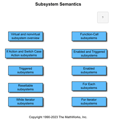
Simulink Subsystem Semantics
This set of examples shows different types of Simulink® Subsystems and what semantics are used when simulating these subsystems. Each example provides a description of the model and the subtleties governing how the model is executed.
Ports
Output
Parameters
Main
Specify the order in which the port that corresponds to the block appears on the parent Subsystem or Model block.
If you add a block that creates another port, the port number is the next available number.
Deleting all blocks associated with a port deletes the port. Other ports are renumbered so that they are sequential and do not skip any numbers.
Specifying a port number that exceeds the number of ports creates a port for that number and for any skipped sequential numbers.
Programmatic Use
To set the block parameter value programmatically, use
the set_param function.
| Parameter: | Port |
| Values: | "1" (default) | real integer in quotes |
| Data Types: | char | string |
Example: set_param("mymodel/Subsystem1/PortBlock",Port="5")
Specify the information displayed on the block icon.
Programmatic Use
Block Parameter:
IconDisplay
|
| Type: character vector |
Values:
'Signal name' | 'Port number' |
'Port number and signal name' |
Default:
'Port number'
|
Select to specify that the block output is the value of the input signal at the previous time step.
Selecting this option enables the software to resolve data dependencies among triggered subsystems that are part of a loop.
The Inport block indicates that this option is selected
by displaying <Lo>.

Dependencies
This parameter is enabled only when the block represents an input port in a triggered subsystem.
Programmatic Use
Block Parameter:
LatchByDelayingOutsideSignal
|
| Type: character vector |
Values:
'on' | 'off' |
Default:
'off'
|
Select to specify that the block latches the input value and prevents it from changing during the execution of the function-call subsystem. For a single function call that is branched to invoke multiple function-call subsystems, this option breaks a loop formed when a signal feeds back from one function-call subsystem into another. Selecting this option prevents any change to the values of a feedback signal from a function-call subsystem that is invoked during the execution of the subsystem that contains this block.
The Inport block indicates that this option is selected
by displaying <Li>.

Dependencies
This option is enabled only when the block represents an input port in a function-call subsystem.
Programmatic Use
Block Parameter:
LatchInputForFeedbackSignals
|
| Type: character vector |
Values:
'on' | 'off' |
Default:
'off'
|
To import, visualize, and map signal and bus data to root-level Inport blocks, click this button. The Root Inport Mapper tool opens.
Dependencies
This button appears only when the block is at the root level for the model.
Signal Attributes
Specify that the input signal produces a function-call event signal.
Select this option if a current model must accept a function-call event signal when referenced in the top model.
Dependencies
To enable this option, the block must be in an asynchronous function call.
The software ignores the value of this parameter when Data type specifies a
Simulink.ValueTypeobject.
Programmatic Use
Block Parameter:
OutputFunctionCall |
| Type: character vector |
Values:
'off' | 'on' |
Default:
'off' |
Lower value of the output range that the software checks.
This number must be a finite real double scalar value.
The software uses this value to perform:
Simulation range checking (see Specify Signal Ranges).
Automatic scaling of fixed-point data types.
Optimization of the code that you generate from the model. This optimization can remove algorithmic code and affect the results of some simulation modes such as SIL or external mode. For more information, see Optimize using the specified minimum and maximum values (Embedded Coder).
Dependencies
The software ignores the value of this parameter when Data type
specifies a Simulink.ValueType or Simulink.Bus object. The
software uses the minimum values specified by the Simulink.ValueType object
or the Simulink.BusElement objects in the Simulink.Bus
object instead.
Programmatic Use
Block Parameter:
OutMin |
| Type: character vector |
Values: '[ ]'|
scalar |
Default: '[ ]' |
Upper value of the output range that the software checks.
This number must be a finite real double scalar value.
The software uses this value to perform:
Simulation range checking (see Specify Signal Ranges).
Automatic scaling of fixed-point data types.
Optimization of the code that you generate from the model. This optimization can remove algorithmic code and affect the results of some simulation modes such as SIL or external mode. For more information, see Optimize using the specified minimum and maximum values (Embedded Coder).
Dependencies
The software ignores the value of this parameter when Data type
specifies a Simulink.ValueType or Simulink.Bus object. The
software uses the maximum values specified by the Simulink.ValueType object
or the Simulink.BusElement objects in the Simulink.Bus
object instead.
Programmatic Use
Block Parameter:
OutMax |
| Type: character vector |
Values: '[ ]'|
scalar |
Default: '[ ]' |
Specify the output data type of the external input. The type can be
inherited, specified directly, or expressed as a data type object, such
as Simulink.NumericType.
The Data Type Assistant helps you set data
attributes. To use the Data Type Assistant, click ![]() . For more information, see Specify Data Types Using Data Type Assistant.
. For more information, see Specify Data Types Using Data Type Assistant.
You can specify any of these options:
Inherited data type
Built-in Simulink® data type — For example, specify
singleoruint8. See Data Types Supported by Simulink.Fixed-point data type — Use the
fixdtfunction. For example, specifyfixdt(1,16,0).Enumerated data type — Use the name of the type preceded by
Enum:. For example, specifyEnum: myEnumType.Bus data type — Use the name of the
Simulink.Busobject preceded byBus:. For example, specifyBus: myBusObject.Simulink image data type — If you have Computer Vision Toolbox™, use the constructor for the
Simulink.ImageType(Computer Vision Toolbox) object and specify the properties to describe the image. By default, the data type uses theSimulink.ImageType(480,640,3)expression that represents the rows, columns, and channels of the image respectively.Value type — Use the name of the
Simulink.ValueTypeobject preceded byValueType:. For example, specifyValueType: windVelocity.Custom data type — Use a MATLAB® expression that specifies the type. For example, you can specify a
Simulink.NumericTypeobject whoseDataTypeModeproperty is set to a value other than'Fixed-point: unspecified scaling'.
When you specify a Simulink.ValueType or
Simulink.Bus object as the data type, some parameters of the
Inport block are ignored. For example, the Min,
Max, and Unit parameters of the
Inport block are ignored. The software uses the corresponding properties of
the Simulink.ValueType object or the Simulink.BusElement objects
in the Simulink.Bus object instead. For example, suppose a block sets
Unit to ft/s. When the Data type of
the block specifies a ValueType object that has m/s as its
unit, the block uses m/s instead of ft/s.
Programmatic Use
Block Parameter:
OutDataTypeStr |
| Type: character vector |
Values: 'Inherit:
auto' | 'double' |
'single' | 'half' |
'int8' | 'uint8' |
'int16' | 'uint16' |
'int32' | 'uint32' |
'int64' | 'uint64' |
'boolean' |
'fixdt(1,16)' |
'fixdt(1,16,0)' |
'fixdt(1,16,2^0,0)' |
'string' | 'Enum: <class
name>' | 'Bus: <object
name>' | 'ValueType: <object
name>' | '<data type
expression>' |
Simulink.ImageType(480,640,3) |
Default: 'Inherit:
auto' |
Select this parameter to prevent the fixed-point tools from overriding the output data type you specify on the block. For more information, see Use Lock Output Data Type Setting (Fixed-Point Designer).
Dependencies
The software ignores the value of this parameter when Data type
specifies a Simulink.ValueType object.
Programmatic Use
Block Parameter:
LockScale |
Values: 'off' |
'on' |
Default: 'off' |
Specify whether the output for a top-level Inport block used to load bus data is virtual or nonvirtual.
Select this parameter to specify a nonvirtual bus output.
Clear this parameter to specify a virtual bus output.
Tips
All signals in a nonvirtual bus must have the same sample time, even if the associated bus object specifies inherited sample time for some elements. Any operation that would result in a nonvirtual bus containing signals with different sample rates generates an error. You cannot load multirate data for a nonvirtual bus. See Modify Sample Times for Nonvirtual Buses for details on how to pass signals with different sample rates into a referenced model as a nonvirtual bus.
To load multirate data for a bus, clear the Output as nonvirtual bus parameter, and set the Sample time parameter to inherited (
-1).For the top model in a model reference hierarchy, code generation creates a C structure to represent the nonvirtual bus output.
For referenced models, select this option to create a C structure in generated code. Otherwise, code generation creates an argument for each leaf element of the bus.
Dependencies
To enable this parameter:
The block must be at the top level of a model.
The Data type block parameter must resolve to a
Simulink.Busobject. For example, set Data type to aSimulink.Busobject or aSimulink.ValueTypeobject that specifies aSimulink.Busobject as its data type.
Programmatic Use
Block Parameter:
BusOutputAsStruct |
| Type: character vector |
Values: 'off' |
'on' |
Default: 'off' |
Specify the physical unit of the input signal to the block. To specify a unit, begin
typing in the text box. As you type, the parameter displays potential matching units.
For a list of supported units, use the showunitslist function.
To constrain the unit system, click the link to the right of the parameter:
If a Unit System Configuration block exists in the component, its dialog box opens. Use that dialog box to specify allowed and disallowed unit systems for the component.
If a Unit System Configuration block does not exist in the component, the model Configuration Parameters dialog box displays. Use that dialog box to specify allowed and disallowed unit systems for the model.
Dependencies
The software ignores the value of this parameter when Data type
specifies a Simulink.ValueType or Simulink.Bus object. The
software uses the units specified by the Simulink.ValueType object or the
Simulink.BusElement objects in the Simulink.Bus object
instead.
Programmatic Use
Block Parameter:
Unit
|
| Type: character vector |
Values:
'inherit' | '<Enter unit>'
|
Default:
'inherit'
|
To specify the physical unit of the input signal to the block
without propagation, use UnitNoProp.
Specify the dimensions of the output signal.
| The port can load data for a signal with any dimensions. The port inherits dimensions from the connected signal. |
| The port can load data for a signal that is a vector of size
|
| The port can load data for a matrix signal having
|
Dependencies
The software ignores the value of this parameter when Data
type specifies a Simulink.ValueType object. The
software uses the dimensions specified by the Simulink.ValueType
object instead.
Programmatic Use
Block Parameter:
PortDimensions |
| Type: character vector |
Values: '-1' | integer |
[integer integer] |
Default: '-1' |
Specify the type of signals allowed for this port. To allow variable-size and
fixed-size signals, select Inherit. To allow only
variable-size signals, select Yes. To allow only fixed-size
signals, select No.
When the signal at this port is a variable-size signal, the Port dimensions parameter specifies the maximum dimensions of the signal.
Dependencies
The software ignores the value of this parameter when Data
type specifies a Simulink.ValueType object. The
software uses the dimensions mode specified by the
Simulink.ValueType object instead.
Programmatic Use
Parameter:
VarSizeSig
|
| Type: character vector |
Value:
'Inherit' | 'No' |
'Yes'
|
Default:
'Inherit'
|
Specify the complexity of the signal output. To inherit the complexity from the
signal that is connected to its input, select auto.
Otherwise, choose a real or complex signal type.
Dependencies
The software ignores the value of this parameter when Data
type specifies a Simulink.ValueType or
Simulink.Bus object. The software uses the complexity specified
by the Simulink.ValueType object or the
Simulink.BusElement objects in the Simulink.Bus
object instead.
Programmatic Use
Block Parameter:
SignalType |
| Type: character vector |
Values:
'auto' | 'real' |
'complex' |
Default:
'auto' |
Execution
Specify the discrete interval between sample time hits or specify another type of
sample time, such as continuous (0) or inherited
(-1). For more options, see Types of Sample Time.
By default, the block inherits its sample time based upon the context of the block within the model.
Programmatic Use
Block Parameter:
SampleTime |
| Type: character vector |
| Values: scalar |
Default:
'-1' |
When loading data from the workspace into a root-level Inport block, specify whether the block linearly interpolates and extrapolates output values at time steps for which no corresponding data exists.
To load discrete data from the workspace:
Set the Sample time to a discrete rate, such as
2.Clear Interpolate data.
For more information, see Control How Models Load Input Data.
The software uses the following interpolation and extrapolation:
For time steps between the first specified data point and the last specified data point — zero-order hold.
For time steps before the first specified data point and after the last specified data point — ground value.
For variable-size signals for time steps before the first specified data point — a
NaNvalue is logged for single or double data types and ground for other data types. For time steps after the last specified data point, the software uses ground values.
Programmatic Use
Block Parameter:
Interpolate
|
| Type: character vector |
Values:
'on' | 'off' |
Default:
'on'
|
Since R2022b
The Events parameter stores the event triggers associated with the port. Event triggers create schedule events to execute one or more partitions in the model based on the runtime activity at a particular location in the model. The schedule for the model specifies the partitions that execute in response to the schedule event, as well as the priority of execution. To configure the schedule for your model, use the Schedule Editor.
Root-level input ports in rate-based models support three types of event triggers that create schedule events in response to input events that relate to the flow of data into the port. You can configure an input port with one event trigger for each input event.
| Input Event | Input Event Description | Event Trigger Object |
|---|---|---|
| Input write | An input write event occurs each time the input port value updates. | simulink.event.InputWrite |
| Input write timeout | An input write timeout event occurs each time the input port value does not update within a specified amount of time. | simulink.event.InputWriteTimeout |
| Input write lost | An input write lost event occurs each time a new input port value overwrites unprocessed data. | simulink.event.InputWriteLost |
Dependencies
This parameter is visible only when the block represents a root-level input port in a rate-based model.
Programmatic Use
Block Parameter:
EventTriggers |
Values:
1-by-1 cell array |
2-by-1 cell array |
3-by-1 cell
array |
Default:
[] |
Block Characteristics
Data Types |
|
Direct Feedthrough |
|
Multidimensional Signals |
|
Variable-Size Signals |
|
Zero-Crossing Detection |
|