Analyze Model Dependencies
Examine models, subsystems, and libraries referenced directly or indirectly by the model using the Dependency Analyzer. Use the dependency graph to identify all required files and products. To package, share, or put your design under source control, create a project from your model. For more details, see Create Project from the Dependency Graph.
Open and Explore Dependency Graph
1. Open the ModelReferenceHierarchy project and the sldemo_mdlref_depgraph model.
2. To open the model dependency graph, on the Modeling tab, click the down arrow to expand the Design section. Under Dependencies, click Dependency Analyzer.
The Dependency Analyzer opens the dependency graph using the Model Hierarchy view by default. To switch to the model instances view, in the Views section, click Model Instances. For more details, see Model Dependency Views.
After you run the first dependency analysis, subsequent analyses incrementally update the results. The Dependency Analyzer determines which files changed since the last analysis and updates the dependency data for those files. To perform a complete analysis, in the Dependency Analyzer, select Analyze > Reanalyze All.
To analyze the dependencies inside add-ons, select Analyze > Add-Ons. For more details about available options, see Dependency Analyzer Scope and Limitations.
3. To view the dependencies laid out horizontally, in the Layout section, click Horizontal.
4. In the dependency graph, double-click a box to open the corresponding model in the Simulink® Editor.
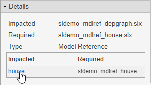
5. To see more information about how two files are related, select their dependency arrow. In the Properties pane, in the Details section, you can see the full paths of the files you are examining, the dependency type, and where the dependency is introduced.

6. To open the file and highlight where the dependency is introduced, in the Details section, click the link under Impacted.
For example, to open the sldemo_mdlref_depgraph model and highlight where the dependency to sldemo_mdlref_house is introduced, select the dependency arrow between sldemo_mdlref_depgraph and sldemo_mdlref_house. In the Properties pane on the right, under Impacted, click house.
Model Dependency Views
You can explore model dependencies using the model hierarchy or the model instances views.
Model Hierarchy View
The Model Hierarchy view shows the model, subsystem, library and data dictionary files referenced by a top model.
A referenced file appears only once in the view even if it is referenced more than once in the model.
In the following illustration, blue boxes represent model files, red boxes represent libraries, and yellow boxes represent subsystem references. Arrows represent dependencies. For example, the arrows in this example indicate that the
aero_guidancemodel references two libraries:aerospaceandsimulink_need_slupdate.
An arrow from a library that points to itself indicates that the library references itself. Blocks in the library reference other blocks in that same library. The example view shows that the libraries
aerospaceandsimulink_need_slupdatereference themselves.Dark red boxes represent protected models (
.slxpfiles). You cannot open or edit protected referenced models. See Reference Protected Models from Third Parties.
Model Instances View
The Model Instances view shows every reference to a model in a model reference hierarchy with the top model at the root of the hierarchy. Boxes represent the top model and its references. See Model References.

If a model hierarchy references the same model more than once, the referenced model appears multiple times in the instance view, once for each reference. This example graph shows that the model reference hierarchy for
sldemo_mdlref_depgraphcontains two references to the modelsldemo_mdlref_F2C.Yellow boxes represent accelerated-mode instances, red boxes represent normal-mode instances, purple boxes represent processor-in-the-loop mode instances, and green boxes represent software-in-the-loop mode instances. See Choose Simulation Modes for Model Hierarchies.
The previous example graph shows that one of the references to
sldemo_mdlref_F2Coperates in normal mode and the other operates in accelerated mode.The Dependency Analyzer detects when a simulation mode is overridden and appends
(Overridden)to the simulation mode. If a referenced model is configured to run in normal mode and it runs in accelerator mode, its simulation mode is overridden. This occurs when another model that runs in accelerator mode directly or indirectly references it.
Find Required Products
To find required products and add-ons for a file in your design, select a box in the dependency graph. The Dependency Analyzer shows the list of required products by your selection in the Products section in the Properties pane.
To find required add-ons for the whole design, click the graph background to clear all selection. Examine the list of products in the Products section in the Properties pane.
To highlight files that use a certain product in the graph, for example
Simulink®, in the Products section, in the
Properties pane, point to product and click the magnifying glass icon
![]() .
.
To go through these files, use the arrows in the search box (e.g., Files
using "productName").
To undo the highlighting, close the search box.
To investigate further, you can list the files that use a product and examine where in
these files the dependency is introduced. In the Products section, in the
Properties pane, point to a product and click the search folder icon
![]() .
.
Export Dependency Analysis Results
To export all the files displayed in the dependency graph, click the graph background to clear the selection on all files. In the Dependency Analyzer toolstrip, in the Export section, click Export. Select from the available options:
Export to Workspace — Save file paths to a variable in the workspace.
Generate Dependency Report — Save dependency analysis results in a printable report (HTML, Word, or PDF).
Package as Archive — Export files in the graph as an archive.
Save as GraphML — Save dependency analysis results as a GraphML file.
Save as Image — Save displayed dependency graph as an image.
You can also export a subset of files in the graph. Select the files, then click Export. The menu displays how many files are selected. The Dependency Analyzer exports only the selected files.

Note
When you use Package as Archive, the Dependency Analyzer includes the selected files and all their dependencies in the archive.
Create Project from the Dependency Graph
To package, share, or put your design under source control, create a project from your model. You can create a project from the model dependency graph.
To create a project from all the files displayed in the dependency graph, click the graph background. This action clears all selected files.
In the Dependency Analyzer toolstrip, in the Export section, click Create Project.
In the Create Project window, click OK.
The Dependency Analyzer creates a project and reloads the graph.
You can also create a project from a subset of files in the graph. Select the files, then click Create Project. The Dependency Analyzer includes the selected files and all their dependencies in the project.