Design Optimization to Meet Step Response Requirements (GUI)
This example shows how to optimize controller parameters to meet step response design requirements using the Response Optimizer app. You specify the design requirements in a Check Step Response Characteristics block.
Model Structure
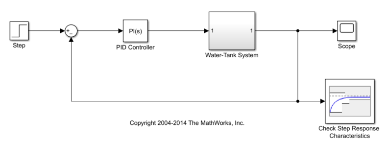
This example uses the watertank_stepinput model. This model includes the nonlinear Water-Tank System plant and a PI controller in a single-loop feedback system.
Open the model.
sys = 'watertank_stepinput';
open_system(sys)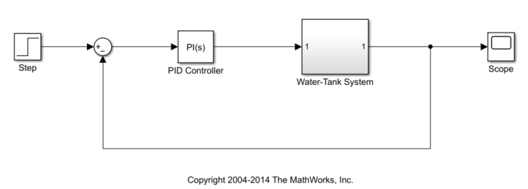
To view the water tank model, open the Water-Tank System subsystem.
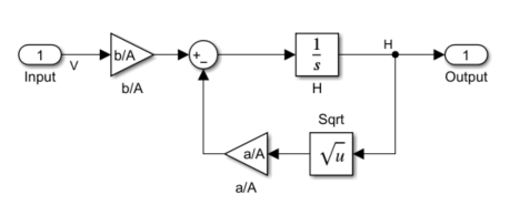
This model represents the following water tank system.
Here:
is the volume of water in the tank.
is the cross-sectional area of the tank.
is the height of water in the tank.
is the voltage applied to the pump.
is a constant related to the flow rate into the tank.
is a constant related to the flow rate out of the tank.
Water enters the tank at the top at a rate proportional to the valve opening. The valve opening is proportional to the voltage, , applied to the pump. The water leaves through an opening in the tank base at a rate that is proportional to the square root of the water height, . The presence of the square root in the water flow rate results in a nonlinear plant. Based on these flow rates, the rate of change of the tank volume is:
Design Requirements
The height of water in the tank, H, must meet the following step response requirements.
Rise time less than 2.5 seconds
Settling time less than 20 seconds
Overshoot less than 5%
Specify Step Response Requirements
To specify step response requirements, add a Check Step Response Characteristics block to the model. To do so, in the Simulink® model window, on Simulation tab, click Library Browser. In the Simulink Design Optimization list, select Signal Constraints.
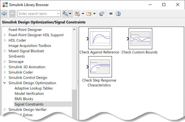
Drag and drop the Check Step Response Characteristics block into the model window and connect the block to the output. The block is connected to the signal for which you want to specify design requirements.
Double-click the Check Step Response Characteristics block to open the block parameters dialog and specify the following requirements:
In Rise time (seconds), enter
2.5.In Settling time (seconds), enter
20.In % Overshoot, enter
5.In Initial value, enter
1.In Final value, enter
2.
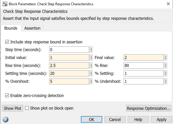
Click OK.
Instead of specifying time-domain requirements in the Check blocks, you can specify them in the Response Optimizer without adding blocks. For an example that uses this approach, see Design Optimization to Track Reference Signal (GUI).
Specify Design Variables
When you optimize the model response, the software modifies the design variable values to meet the design requirements. You specify which model parameters the software can modify.
To open a Response Optimizer session for this model, in the Simulink model window, in the Apps gallery, click Response Optimizer. Alternatively, in the Check Step Response Characteristics block parameters dialog, click Response Optimization.
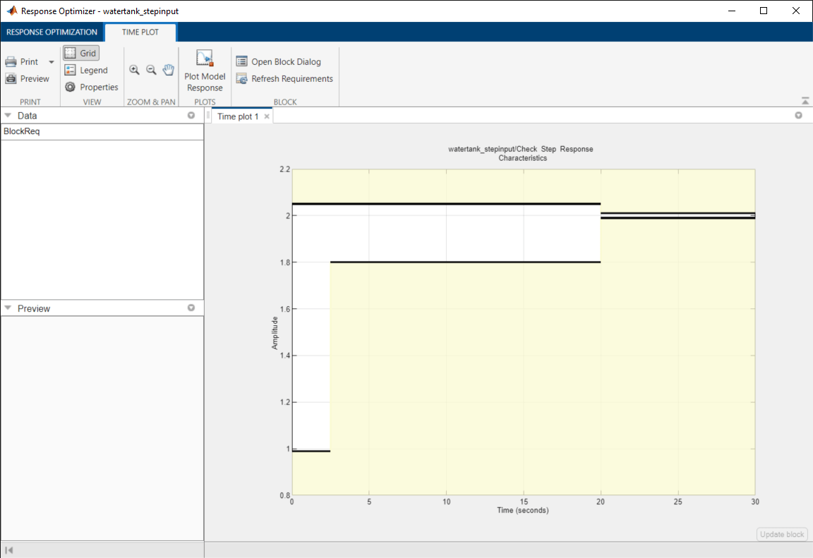
The region bounded by black line segments in Time plot 1 shows the step response requirements that you specified in the Check Step Response Characteristics block.
To create a set of design variables, in the Design Variables Set list, select New.
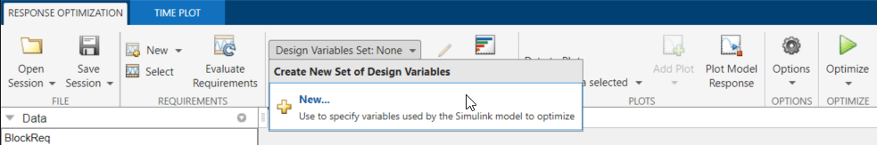
The Create Design Variables Set dialog box shows model parameters that you can use as design variables and indicates their locations within the model.
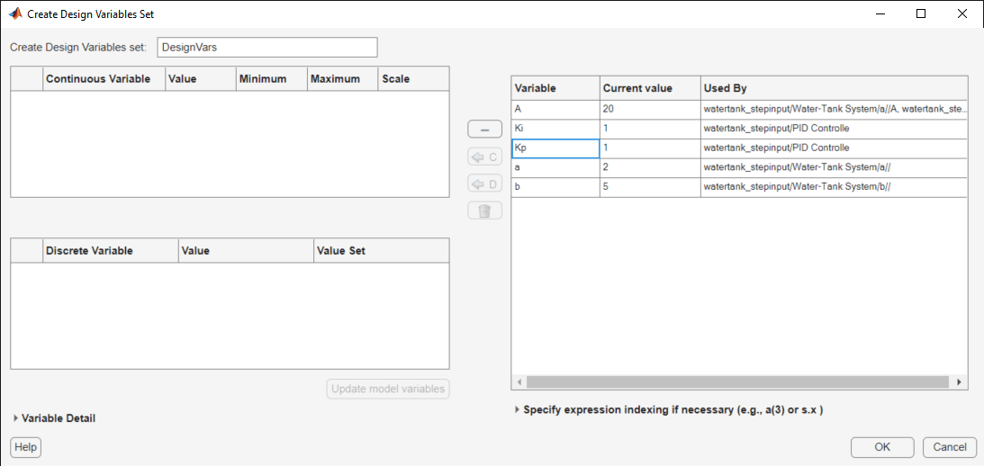
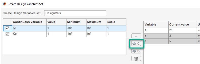
To add parameters to the design variable set, select Ki and Kp, and click ![]() .
.
The design variables list displays the following variable settings:
Variable — Variable name
Value — Current variable value
Minimum and Maximum — Variable bounds
Scale — Scaling factor for the variable
Limit the design variables to positive values. To do so, enter 0 for the minimum value of each variable in the corresponding Minimum field and press Enter on your keyboard.
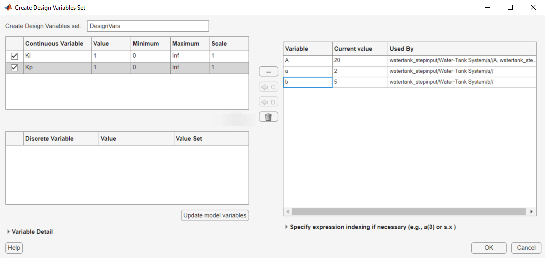
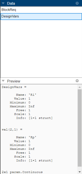
Click OK. A new design variable DesignVars is created and appears in the Data area of Response Optimizer. You can click the variable to view its contents in the Variable Preview area.
If your model has many parameters, you can first use sensitivity analysis to determine the most influential parameters to optimize, or to obtain initial guesses for the design variables. For more information, see What is Sensitivity Analysis? Using the Sensitivity Analyzer app, you can explore the response optimization design space by altering the design variables, identify the parameters that most influence the optimization problem, and compute initial values.
Optimize Model Response
To view the current response of the model, click Plot Model Response.
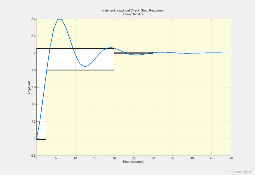
The plot shows the model output, depicted by the blue line, lies outside the region of the specified step response.
To optimize the model response, click Optimize. The default optimization solver Gradient descent (fmincon) modifies the design variables at each iteration so that the simulated response lies within the design requirement line segments. For more information, see How the Optimization Algorithm Formulates Minimization Problems.
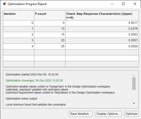
The message Optimization converged in the Optimization Progress Report indicates that the optimization solver found a solution that meets the design requirements within the tolerances and parameter bounds. For more information about the outputs displayed in the optimization, see Iterative Display.
Verify that the model output meets the step response requirements.
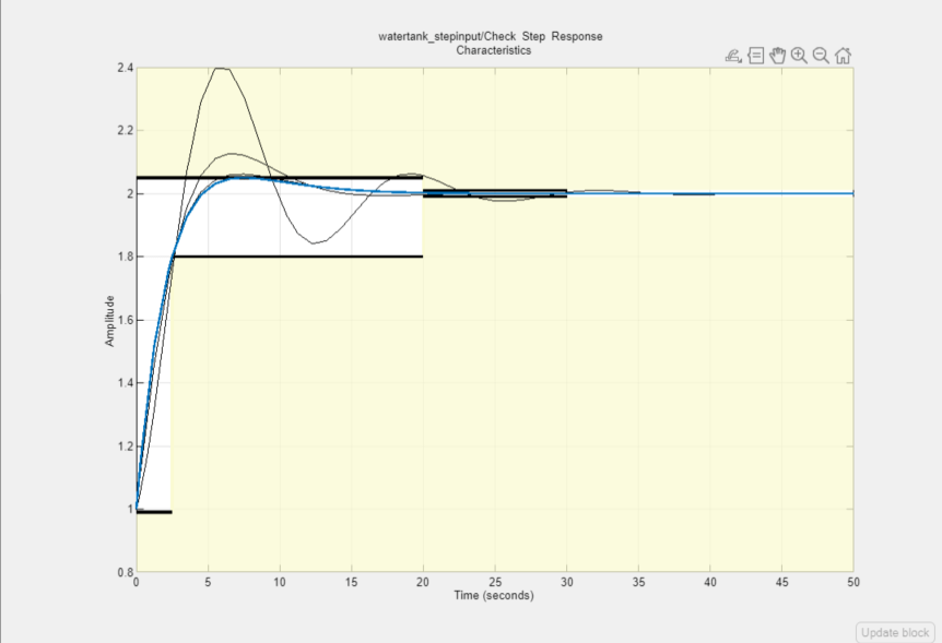
The plot displays the last five iterations. The final response using the optimized variable parameter appears as the thick blue line. The optimized response lies in the white region bounded by the design requirement line segments and thus meets the requirements.
To view the optimized parameter values, click DesignVars in Model Workspace and view the updated values in the Variable Preview area. The optimized values of the design variables are automatically updated in the Simulink model.
Save the Session
After you optimize the model response to meet design requirements, you can save the Response Optimizer session which includes the optimized parameter values.
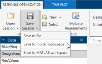
In the Response Optimizer, in the Response Optimization tab, in the Save Session drop-down list, select Save to model workspace.
In the Save Session window, specify the session name in the Session field.
To open the saved session, in the Response Optimizer for the model, in the Open Session drop-down list, click the Open from model workspace option.
Related Topics
You can also select a web site from the following list:
Americas
- América Latina (Español)
- Canada (English)
- United States (English)
Europe
- Belgium (English)
- Denmark (English)
- Deutschland (Deutsch)
- España (Español)
- Finland (English)
- France (Français)
- Ireland (English)
- Italia (Italiano)
- Luxembourg (English)
- Netherlands (English)
- Norway (English)
- Österreich (Deutsch)
- Portugal (English)
- Sweden (English)
- Switzerland
- United Kingdom (English)