Schedule Chart Actions by Using Temporal Logic
To define the behavior of a Stateflow chart in terms of simulation time, include temporal logic operators in the state and transition actions of the chart. Temporal logic operators are built-in functions that tell you the length of time that a state remains active or that a Boolean condition remains true. With temporal logic, you can control the timing of:
Transitions between states
Function calls
Changes in variable values
These are the most common operators for absolute-time temporal logic:
after—after(n,sec)returnstrueifnseconds of simulation time have elapsed since the state that contains the operator or the source state of the transition that contains the operator became active. Otherwise, the operator returnsfalse. This operator supports event-based temporal logic and absolute-time temporal logic in seconds (sec), milliseconds (msec), and microseconds (usec).elapsed—elapsed(sec)returns the number of seconds of simulation time that have elapsed since the activation of the associated state.duration—duration(C)returns the number of seconds of simulation time that have elapsed since the Boolean conditionCbecomestrue.
Model a Bang-Bang Temperature Controller
This example uses temporal logic to model a bang-bang controller that regulates the internal temperature of a boiler.
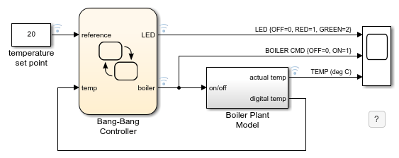
The example consists of a Stateflow chart and a Simulink® subsystem. The Bang-Bang Controller chart compares the current boiler temperature to a reference set point and determines whether to turn on the boiler. The Boiler Plant Model subsystem models the dynamics inside the boiler by increasing or decreasing its temperature according to the status of the controller. Then, the chart uses the boiler temperature for the next step in the simulation.
The Bang-Bang Controller chart uses the temporal logic operator after to:
Regulate the timing of the bang-bang cycle as the boiler alternates between on and off.
Control a status LED that flashes at different rates depending on the operating mode of the boiler.
The timers defining the behavior of the boiler and LED subsystems operate independently of one another without blocking or disrupting the simulation of the controller.
Timing of Bang-Bang Cycle
The Bang-Bang Controller chart contains a pair of substates that represent the two operating modes of the boiler, On and Off. The chart uses the active state output data boiler to indicate which substate is active.
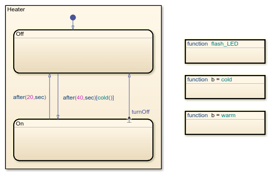
The conditions on the transitions between the On and Off substates define the behavior of the bang-bang controller:
On the first transition from
OntoOff, the conditionafter(20,sec)turns the boiler off after it is on for 20 seconds.On the transition from
OfftoOn, the conditionafter(40,sec)[cold()]turns the boiler on when the graphical functioncold()indicates that the boiler temperature is below the reference set point for at least 40 seconds.On the second transition from
OntoOff, the trivial condition turns the boiler off when the internal transition logic in theOnstate determines that the boiler temperature is at or above the reference set point.
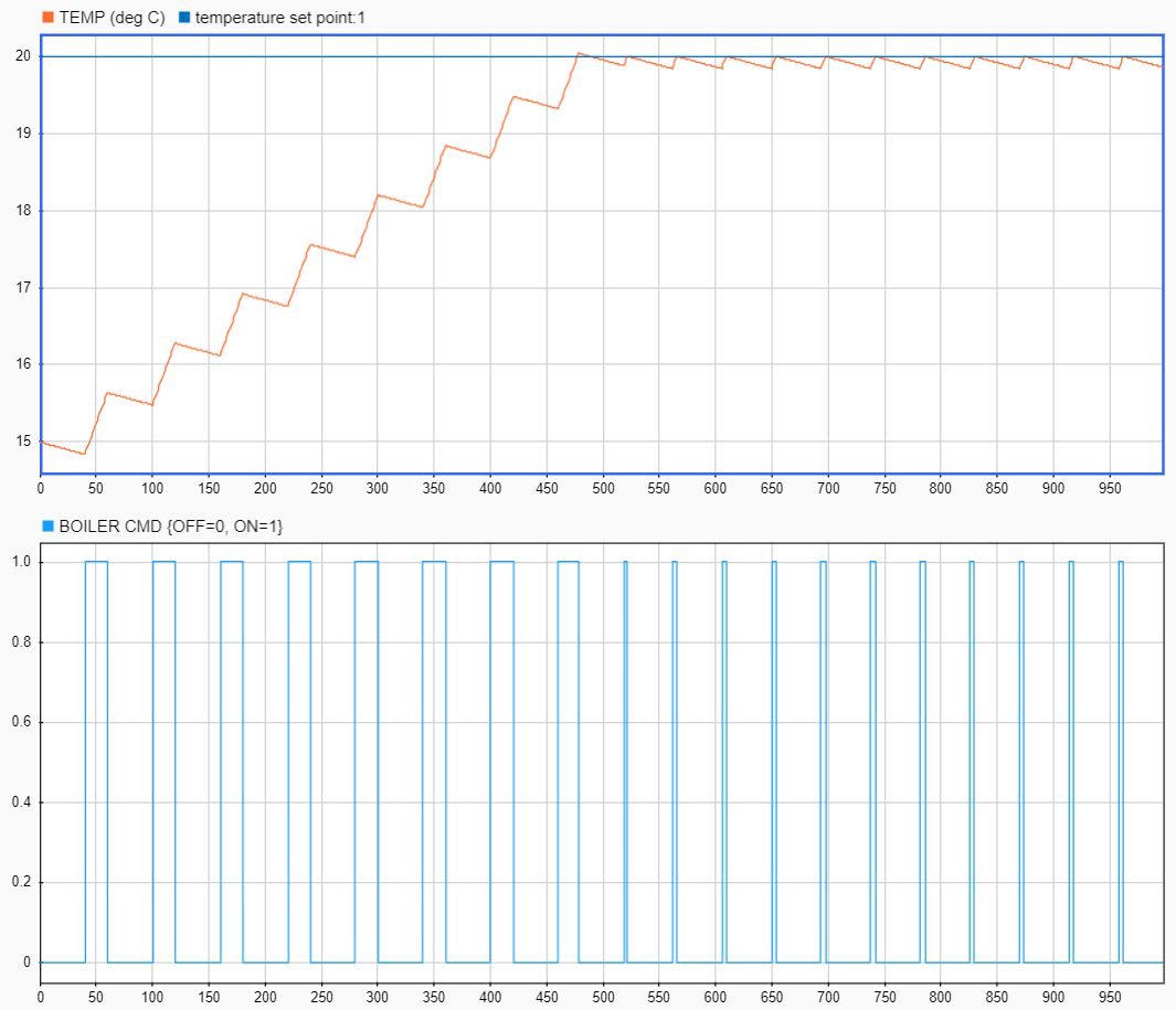
As a result of these transition actions, the timing of the bang-bang cycle depends on the current temperature of the boiler. At the start of the simulation, when the boiler is cold, the controller spends 40 seconds in the Off state and 20 seconds in the On state. At time  seconds, the temperature of the boiler reaches the reference set point. From that point, the boiler has to compensate only for the heat lost while in the
 Off state. The controller then spends 40 seconds in the Off state and 4 seconds in the On state.
Timing of Status LED
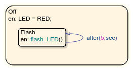
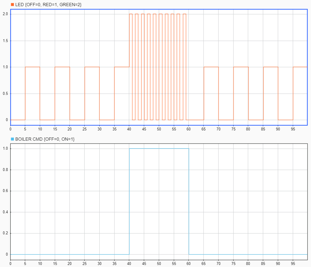
The Off state contains a substate Flash with a self-loop transition triggered by the action after(5,sec). Because of this transition, when the Off state is active, the substate executes its entry action and calls the graphical function flash_LED every 5 seconds. The function toggles the value of the output symbol LED between 0 and 1.
The On state calls the graphical function flash_LED as a combined entry, during state action. When the On state is active, this action calls the function at every time step of the simulation to toggle the value of the output symbol LED between 0 and 2.

As a result, the timing of the status LED depends on the operating mode of the boiler. For example:
From
 to
to  seconds, the boiler is off and the LED signal alternates between 0 and 1 every 5 seconds.
From
to  seconds, the boiler is on and the LED signal alternates between 0 and 2 every second.
From
to  seconds, the boiler is off and the LED signal alternates between 0 and 1 every 5 seconds.
Explore the Example
Use additional temporal logic to investigate how the timing of the bang-bang cycle changes as the temperature of the boiler approaches the reference set point.
1. Enter new state actions that call the elapsed and duration operators:
In the
Onstate, setTimer1to be the length of time that theOnstate is active:
en,du,ex: Timer1 = elapsed(sec);
In the
Offstate, setTimer2to be the length of time that the boiler temperature is at or above the reference set point:
en,du,ex: Timer2 = duration(temp>=reference);
2. In the Symbols pane, click Resolve Undefined Symbols. The Stateflow Editor resolves the symbols Timer1 and Timer2 as output data.
3. Enable logging for Timer1 and Timer2. In the Symbols pane, select each symbol. Then, in the Property Inspector, under Logging, select Log signal data.
4. In the Simulation tab, click Run.
5. In the Simulation tab, under Review Results, click Data Inspector.
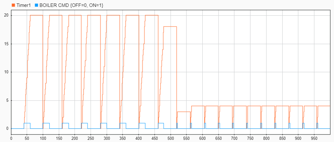
6. In the Simulation Data Inspector, display the signals boiler and Timer1 in the same set of axes. The plot shows that:
The
Onphase of the bang-bang cycle typically lasts 20 seconds when the boiler is cold and 4 seconds when the boiler is warm.The first time that the boiler reaches the reference temperature, the cycle is interrupted prematurely and the controller stays in the
Onstate for only 18 seconds.When the boiler is warm, the first cycle is slightly shorter than the subsequent cycles, as the controller stays in the
Onstate for only 3 seconds.
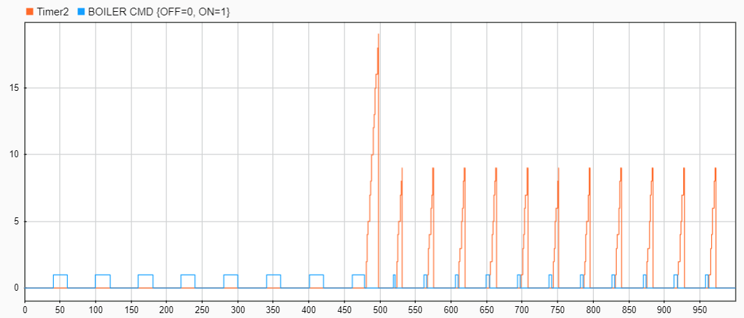
7. In the Simulation Data Inspector, display the signals boiler and Timer2 in the same set of axes. The plot shows that:
Once the boiler is warm, it typically takes 9 seconds to cool in the
Offphase of the bang-bang cycle.The first time that the boiler reaches the reference temperature, it takes 19 seconds to cool, which is more than twice as long as the other cycles.
The shorter cycle and longer cooling time are a consequence of the substate hierarchy inside the On state. When the boiler reaches the reference temperature for the first time, the transition from HIGH to NORM keeps the controller on for an extra time step, which results in a warmer-than-normal boiler. In later cycles, the history junction causes the On phase to start with an active NORM substate. The controller then turns off immediately after the boiler reaches the reference temperature, which results in a cooler boiler.
Related Topics
You can also select a web site from the following list:
Americas
- América Latina (Español)
- Canada (English)
- United States (English)
Europe
- Belgium (English)
- Denmark (English)
- Deutschland (Deutsch)
- España (Español)
- Finland (English)
- France (Français)
- Ireland (English)
- Italia (Italiano)
- Luxembourg (English)
- Netherlands (English)
- Norway (English)
- Österreich (Deutsch)
- Portugal (English)
- Sweden (English)
- Switzerland
- United Kingdom (English)