Downlink Control Processing and Procedures
This example describes the blind search decoding of the physical downlink control channel (PDCCH) for 5G New Radio communications system. Building on the tutorial Modeling Downlink Control Information, this example introduces the concepts of control resource set (CORESET) and search spaces, their generic specification and shows how a PDCCH instance is mapped to one of several candidates within a search space. To recover the transmitted control information at the receiver, the example performs a blind search over the set of candidates.
System Parameters
Set system parameters corresponding to the carrier, CORESET, search space set, and PDCCH instance respectively.
rng(111);                               % Set RNG state for repeatability

% Carrier configuration
carrier = nrCarrierConfig;
carrier.NCellID = 2;                    % Cell identity
carrier.SubcarrierSpacing = 30;         % Carrier/BWP Subcarrier spacing
carrier.CyclicPrefix = 'normal';        % Cyclic prefix
carrier.NSlot      = 0;                 % Slot counter
carrier.NFrame     = 0;                 % Frame counter
carrier.NStartGrid = 10;                % Carrier offset
carrier.NSizeGrid  = 48;                % Size of carrier in RB

% CORESET configuration
coreset = nrCORESETConfig;
coreset.CORESETID = 1;                  % CORESET ID (0...11)
coreset.FrequencyResources = ones(1,4); % 6 RB sized
coreset.Duration = 1;                   % CORESET symbol duration (1,2,3)
coreset.CCEREGMapping = 'interleaved';  % CORESET Mapping
coreset.REGBundleSize = 2;              % L (2,6) or (3,6)
coreset.InterleaverSize = 2;            % R (2,3,6)
coreset.ShiftIndex = carrier.NCellID;   % default to NCellID

% Search space configuration
ss = nrSearchSpaceConfig;
ss.CORESETID = 1;                       % Associated CORESET ID (0...11)
ss.SearchSpaceType = 'ue';              % 'ue', 'common'
ss.StartSymbolWithinSlot = 0;           % Starting symbol in slot
ss.SlotPeriodAndOffset = [1 0];         % Search space period and offset
ss.Duration = 1;                        % Search space duration in slots
ss.NumCandidates = [4 2 1 0 0];         % For (1,2,4,8,16) levels respectively

% PDCCH configuration
pdcch = nrPDCCHConfig;
pdcch.NStartBWP  = 10;                  % BWP offset wrt CRB 0
pdcch.NSizeBWP   = 48;                  % Size of BWP in resource blocks
pdcch.CORESET = coreset;                % Associated CORESET
pdcch.SearchSpace = ss;                 % Associated SearchSpace
pdcch.RNTI = 1;                         % C-RNTI
pdcch.DMRSScramblingID = [];            % Use carrier.NCellID instead
pdcch.AggregationLevel = 4;             % Number of CCEs in PDCCH (1,2,4,8,16)
pdcch.AllocatedCandidate = 1;           % 1-based scalar
This example assumes single slot processing, using a single bandwidth part with a single PDCCH transmission for an associated CORESET and search space set.
For more information on waveform generation with multiple physical channels, see the 5G NR Downlink Vector Waveform Generation example.
PDCCH Bit Capacity
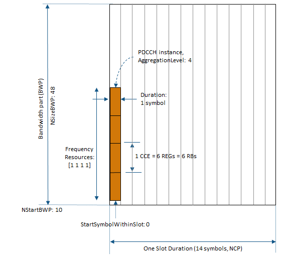
The bit capacity for a PDCCH instance is determined based on the number of control-channel elements (CCE) configured for the PDCCH. A CCE consists of six resource-element groups (REGs) where a REG equals one resource block (RB) during one OFDM symbol.
% Number of bits for PDCCH resources and actual indices
[ind,dmrs,dmrsInd] = nrPDCCHResources(carrier,pdcch);
E = 2*numel(ind);
DCI Encoding
The nrDCIEncode function encodes the DCI message bits based on a downlink format. DCI encoding includes the stages of CRC attachment, polar encoding and rate matching the codeword to the PDCCH bit capacity E.
K = 64;                             % Number of DCI message bits
dciBits = randi([0 1],K,1,'int8');

dciCW = nrDCIEncode(dciBits,pdcch.RNTI,E);
PDCCH Symbol Generation and Mapping
The nrPDCCH function maps the encoded DCI bits onto the physical downlink control channel (PDCCH). The function returns the scrambled, QPSK-modulated symbols. The scrambling accounts for the user-specific parameters.
if isempty(pdcch.DMRSScramblingID)
    nID = carrier.NCellID;
else
    nID = pdcch.DMRSScramblingID;
end
sym = nrPDCCH(dciCW,nID,pdcch.RNTI);
The PDCCH symbols are then mapped to the resource elements corresponding to the allocated candidate within an OFDM grid. The resource grid also contains PDSCH and PBCH symbols, and other reference signal elements. For simplicity, this example only additionally maps the PDCCH DM-RS symbols to the grid.
carrierGrid = nrResourceGrid(carrier);
carrierGrid(ind) = sym;                 % PDCCH symbols
carrierGrid(dmrsInd) = dmrs;            % PDCCH DM-RS
For a resource grid spanning the whole bandwidth part and a single slot, this figure shows some of the CORESET, search space set and PDCCH instance parameters for the selected example configuration.
OFDM Modulation
OFDM modulate the carrier grid. Specify no windowing for the slot-based processing.
[wave,winfo] = nrOFDMModulate(carrier,carrierGrid,'Windowing',0);
Fading Channel
Transmit the generated waveform over a TDL fading channel with delay profile A and a delay spread of 30 ns.
channel = nrTDLChannel;
channel.DelayProfile = 'TDL-A';
channel.DelaySpread = 30e-9;
channel.NumTransmitAntennas = 1;
channel.NumReceiveAntennas = 1;
channel.SampleRate = winfo.SampleRate;

chInfo = info(channel);
maxChDelay = chInfo.MaximumChannelDelay;
txWave = [wave; zeros(maxChDelay, size(wave,2))];

rxWave = channel(txWave);
Noise Addition
Add white Gaussian noise with the specified level to the received signal, taking into account the coding rate, QPSK modulation, and sampling rate.
EbNo = 6;                            % in dB
bps = 2;                             % bits per symbol, 2 for QPSK
EsNo = EbNo + 10*log10(bps);
snrdB = EsNo + 10*log10(K/E);
noiseVar = 10.^(-snrdB/10);          % assumes unit signal power
N0 = sqrt(noiseVar)/sqrt(2*winfo.Nfft);
noise = N0 * complex(randn(size(rxWave)),randn(size(rxWave)));
rxWaveN = rxWave + noise;
Blind PDCCH and DCI Decoding
The UE does not have information about the detailed control channel structure. Therefore, the UE decodes the received PDCCH symbols blindly by monitoring a set of PDCCH candidates for each slot using the UE's RNTI to identify the right candidate (or instance).
Monitoring a candidate implies attempting to decode a set of resource elements corresponding to the candidate by checking if the returned checksum is zero for the known RNTI (UE). Use the nrPDCCHSpace function to determine all candidates specified by the search space set in terms of the PDCCH resource element indices, corresponding DM-RS symbols and indices.
For each candidate, the front-end recovery includes
timing offset estimation based on the DM-RS symbols using the function
nrTimingEstimate,OFDM demodulation using the function
nrOFDMDemodulate,channel estimation based on the DM-RS symbols using the function
nrChannelEstimate, andMMSE equalization using the function
nrEqualizeMMSE
to yield the equalized candidate PDCCH symbols.
The equalized symbols per candidate are demodulated with known user-specific parameters and channel noise variance using the nrPDCCHDecode function.
For an instance of the received PDCCH codeword, the nrDCIDecode function includes the stages of rate recovery, polar decoding, and CRC decoding. If the output mask value is zero, the PDCCH is decoded successfully and the UE can process the DCI message.
In this example, the receiver assumes knowledge of the DCI format and the DCI payload size K. In practice, even these would be searched for in an outer loop over all supported formats with respective bit lengths per format.
listLen = 8;                         % polar decoding list length

% Get all possible candidates
[allInd,allDMRS,allDMRSInd] = nrPDCCHSpace(carrier,pdcch);

% Loop over all supported aggregation levels
decoded = false;
for alIdx = 1:5

    % Loop over all candidates at each aggregation level
    for cIdx = 1:pdcch.SearchSpace.NumCandidates(alIdx)

        % Get candidate
        cSymIdx = allInd{alIdx}(:,cIdx);
        cDMRS = allDMRS{alIdx}(:,cIdx);
        cDMRSInd = allDMRSInd{alIdx}(:,cIdx);

        % Timing estimate
        offset = nrTimingEstimate(carrier,rxWaveN,cDMRSInd,cDMRS);
        if offset > maxChDelay
            offset = 0;
        end
        rxWaveS = rxWaveN(1+offset:end,:);

        % OFDM demodulate the carrier
        rxCarrGrid = nrOFDMDemodulate(carrier,rxWaveS);

        % Channel estimate
        [hest,nVar] = nrChannelEstimate(carrier,rxCarrGrid,cDMRSInd,cDMRS);
        [rxSym,pdcchHest] = nrExtractResources(cSymIdx,rxCarrGrid,hest);

        % Equalization
        [pdcchEq,csi] = nrEqualizeMMSE(rxSym,pdcchHest,nVar);

        % Demodulate
        rxCW = nrPDCCHDecode(pdcchEq,nID,pdcch.RNTI,nVar);

        % Apply CSI
        csiRep = repmat(csi.',2,1);
        scalRxCW = rxCW.*csiRep(:);

        % Decode
        [decDCIBits,errFlag] = nrDCIDecode(scalRxCW,K,listLen,pdcch.RNTI);

        if isequal(errFlag,0)
            disp(['Decoded candidate #' num2str(cIdx)  ...
                ' at aggregation level ' num2str(2^(alIdx-1)) ...
                ' in slot'])
            decoded = true;
            if isequal(decDCIBits,dciBits)
                disp('   Recovered DCI bits with no errors');
            else
                disp('   Recovered DCI bits with errors');
            end
            break;
        end
    end
    % Dont loop over other aggregation levels if RNTI matched
    if decoded
        break;
    end
end
Decoded candidate #1 at aggregation level 4 in slot
   Recovered DCI bits with no errors
For the chosen system parameters, the decoded information matches the transmitted information bits.
The example searched over all candidates within a single search space set as specified by the ss configuration parameter. Search over multiple search space sets would require another external loop over all the sets defined.
Selected References
3GPP TS 38.211. "NR; Physical channels and modulation" 3rd Generation Partnership Project; Technical Specification Group Radio Access Network.
3GPP TS 38.212. "NR; Multiplexing and channel coding" 3rd Generation Partnership Project; Technical Specification Group Radio Access Network.
3GPP TS 38.213. "NR; Physical layer procedures for control" 3rd Generation Partnership Project; Technical Specification Group Radio Access Network.