Modeling and Testing an NR RF Receiver with LTE Interference
The example shows how to characterize the impact of RF impairments in the RF reception of a new radio (NR) waveform when coexisting with a long-term evolution (LTE) interference. The baseband waveforms are generated using 5G Toolbox™ and LTE Toolbox™, and the RF receiver is modeled using RF Blockset™.
Introduction
This example characterizes the impact of LTE interference on the RF reception of an NR waveform. To evaluate the impact of the interference, the example performs these measurements:
Error vector magnitude (EVM): vector difference at a given time between the ideal (transmitted) signal and the measured (received) signal. Annex B and Annex C of TS 38.104 define an alternative method for computing the EVM in FR1 and FR2, respectively.
Adjacent channel leakage ratio (ACLR): measure of the amount of power leaking into adjacent channels. It is defined as the ratio of the filtered mean power centered on the assigned channel frequency to the filtered mean power centered on an adjacent channel frequency.
Occupied bandwidth: bandwidth that contains 99% of the total integrated power of the signal, centered on the assigned channel frequency.
Channel power: filtered mean power centered on the assigned channel frequency.
The impact of the receiver RF impairments such as phase noise and amplifier nonlinearities are also considered.
The example works on a subframe by subframe basis and uses a Simulink model to perform these steps:
Generate the baseband NR waveform using 5G Toolbox features.
Generate the baseband LTE waveform (interference) using LTE Toolbox features.
Match the sampling rate of the two signals by using the Sample-Rate Match block.
To capture spectral regrowth, oversample the waveforms by a factor of 4 or 5 by using the FIR Interpolation block.
Import the baseband waveforms into the RF Receiver Subsystem block implemented by using RF Blockset blocks. The model provides an RF frequency to each waveform to carry the baseband information in RF Blockset.
Model the effects of downconverting the NR waveform to an intermediate frequency by using the RF Receiver Subsystem block. This block models the impairments introduced by an RF receiver using RF Blockset blocks.
Calculate the ACLR/ACPR, occupied bandwidth, and channel power using the Spectrum Analyzer block.
Downsample the NR waveform by using an FIR Decimation block to compensate for the upsampling performed by the FIR Interpolation block.
Downsample the NR waveform by using an FIR Rate Conversion block to compensate for any upsampling performed by the Sample-Rate Match block.
Extract the data symbols and measure the EVM by demodulating the baseband waveform.
The Simulink model uses 5G Toolbox, LTE Toolbox, and DSP System Toolbox™ features to process the baseband waveforms (steps 1-4 and 7-10) and uses RF Blockset blocks to model the RF receiver (steps 5 and 6). This model supports Normal and Accelerator simulation modes.
Simulink Model Structure
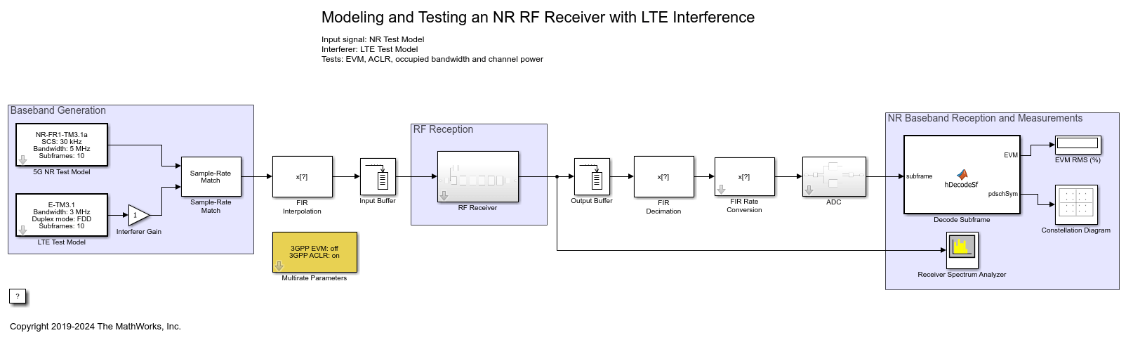
The model contains three main parts:
Baseband Generation: generates the baseband NR and LTE waveforms
RF Reception: models the effects of combining both waveforms in the RF domain and downconverting the NR waveform to an intermediate frequency
NR Baseband Reception and Measurements: performs the RF measurements and calculates EVM by demodulating the NR baseband waveform
modelName = 'NewRadioRFReceiverWithLTEInterferenceModel';
open_system(modelName);
Baseband Generation
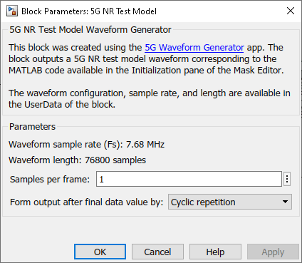
The 5G NR Test Model block transmits the standard-compliant 5G NR test model 3.1 (NR-TM3.1) waveform for frequency range 1 (FR1), as defined in TS 38.141-1. This block is generated using the 5G Waveform Generator app. You can access the waveform configuration parameters in the user data of the block. This example uses the InitFcn in the Model callbacks to store the structure available in the user data in a Base Workspace variable, NRInfo. For more information about this block, see Waveform From Wireless Waveform Generator App.
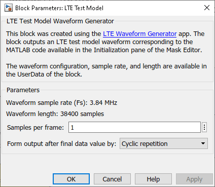
Similarly, the LTE Test Model block transmits the standard-compliant LTE test model 3.1 (E-TM3.1) waveform, as defined in TS 36.141. This block is generated using the LTE Waveform Generator (LTE Toolbox) app. The example also uses the InitFcn in the Model callbacks to store the E-TM configuration available in the block user data in a Base Workspace variable, LTEInfo. For more information about this block, see Waveform From Wireless Waveform Generator App (LTE Toolbox).
The Interferer Gain block controls the level of the LTE interference. You can disable the interference by setting this gain to 0.
The Sample-Rate Match block upsamples the waveform with lower sample rate to match the sample rate of the other waveform. The waveforms must have the same sample rate when combining the waveforms in the RF Receiver block. The Sample-Rate Match block also concatenates both waveforms horizontally, one column per waveform.
To capture spectral regrowth, the FIR Interpolation block oversamples and filters both waveforms. The Multirate Parameters block provides an interface to configure the parameters of the FIR Interpolation and Decimation blocks.
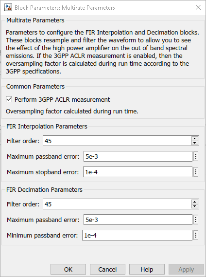
The Multirate Parameters block also provides the option to enable or disable the 3GPP TS 38.141-1 ACLR test. To visualize the spectral regrowth, the ACLR test oversamples the waveform. If the Perform 3GPP ACLR measurement parameter of the Multirate Parameters block is enabled, the oversampling factor depends on the waveform configuration and is set such that the generated signal is capable of representing first and second adjacent channels. To specify the Oversampling factor, disable the 3GPP ACLR test. The Oversampling factor parameter defines the Interpolation factor in the FIR Interpolation block and the Decimation factor in the FIR Decimation block.
RF Reception
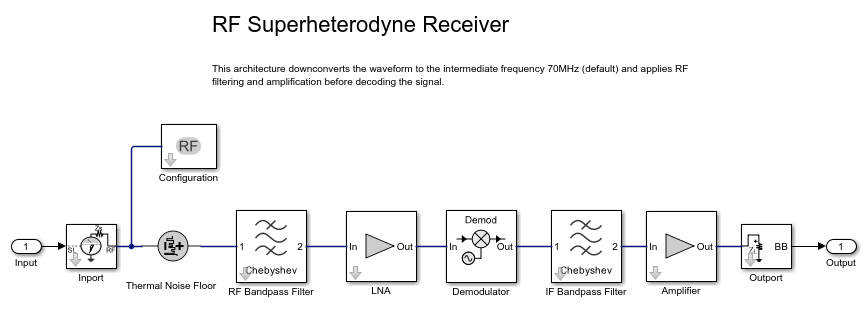
The RF Receiver Subsystem block is based on a superheterodyne receiver architecture. This architecture models the effects of downconverting the NR waveform to an intermediate frequency by characterizing these RF components:
Bandpass filters
Low noise amplifiers
Demodulator consisting of mixers, phase shifter, and local oscillator
set_param(modelName,'Open','off');
set_param([modelName '/RF Receiver'],'Open','on');
Use an Input Buffer block to send one sample at a time to the RF Receiver Subsystem block.
The Inport block inside the RF Receiver Subsystem block converts the two concatenated Simulink complex baseband waveforms into the RF Blockset Circuit Envelope simulation environment. The Carrier frequencies parameter of the Inport block specifies the center frequency of the carriers in the RF Blockset domain. The Outport block converts the RF Blockset signals back into Simulink complex baseband.
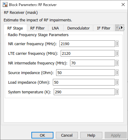
You can configure the RF Receiver components using the RF Receiver Subsystem block mask.
The RF Receiver Subsystem block models typical impairments, including:
Phase noise as a secondary effect directly related to the thermal noise within the active devices of the oscillator.
Amplifier nonlinearities due to DC power limitation when the amplifier works in saturation region.
Impedance mismatch resulting in signal reflection or an inefficient power transfer
Before sending the samples onto the Decode Subframe block, the Output Buffer (after the RF Receiver) buffers all samples within a subframe. At the output of the Output Buffer block, the FIR Decimation and the FIR Rate Conversion blocks downsample the NR waveform back to the original sampling rate.
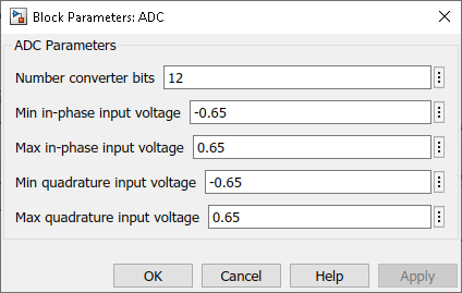
The ADC Subsystem block models the effect of digitizing the signal. You can modify the parameters of the blocks inside the ADC Subsystem block using its mask.
The use of buffers in the model generates time delays. As the duration of the delay is equivalent to the transmission of a subframe, the Decode Subframe block does not demodulate the first received subframe.
NR Baseband Reception and Measurements
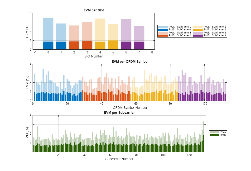
The Decode Subframe block performs OFDM demodulation of the received subframe, channel estimation, and equalization to recover and plot the PDSCH symbols in the Constellation Diagram. This block also averages the EVM over time and frequency and plots these values:
EVM per OFDM symbol: EVM averaged over each OFDM symbol.
EVM per slot: EVM averaged over the allocated PDSCH symbols within a slot.
EVM per subcarrier: EVM averaged over the allocated PDSCH symbols within a subcarrier.
Overall EVM: EVM averaged over all the allocated PDSCH symbols transmitted.
Annex B and Annex C of TS 38.104 define an alternative method for computing the EVM in FR1 and FR2, respectively. You can enable this method by enabling Perform 3GPP EVM measurement parameter of the Multirate Parameters block.
The Spectrum Analyzer block provides frequency-domain measurements such as ACLR (referred to as ACPR) and occupied bandwidth. If you disable the Perform 3GPP ACLR measurement parameter of the Multirate Parameters block, you can select the oversampling factor and the Spectrum Analyzer block measures the occupied bandwidth.
The Decode Subframe block discards the first received subframe (1 ms) due to processing delays. Therefore, to receive one frame, you must simulate 11 ms for FDD (10 ms for the frame plus 1 ms for the initially discarded subframe period). If the simulation time is longer than 11 ms, the 5G NR Test Model block cyclically transmits the same NR frame. Similarly, the LTE Test Model block cyclically transmits the same LTE frame.
Model Performance
To characterize the impact of the LTE interference on the NR reception you can compare the EVM and ACLR results for two different cases: 1) NR transmission without LTE interference and 2) NR transmission with LTE interference.
Without LTE interference (Interferer gain = 0). To eliminate the LTE interference, set the Gain parameter of the Interferer Gain block to 0. Run the simulation to capture, for instance, 4 subframes (5 ms). During simulation, the model displays the EVM and ACLR measurements and the constellation diagram.
set_param([modelName '/Interferer Gain'],'Gain','0');
sim(modelName);
EVM stats for BWP idx : 1
PDSCH RMS EVM, Peak EVM, slot 0: 0.862 3.446%
DM-RS RMS EVM, Peak EVM, slot 0: 0.647 1.553%
PDSCH RMS EVM, Peak EVM, slot 1: 0.840 2.838%
DM-RS RMS EVM, Peak EVM, slot 1: 0.502 1.159%
Averaged overall PDSCH RMS EVM: 0.851%
Overall PDSCH Peak EVM = 3.4459%
EVM stats for BWP idx : 1
PDSCH RMS EVM, Peak EVM, slot 2: 0.893 2.640%
DM-RS RMS EVM, Peak EVM, slot 2: 0.729 1.644%
PDSCH RMS EVM, Peak EVM, slot 3: 0.920 3.010%
DM-RS RMS EVM, Peak EVM, slot 3: 0.693 1.583%
Averaged overall PDSCH RMS EVM: 0.906%
Overall PDSCH Peak EVM = 3.0096%
EVM stats for BWP idx : 1
PDSCH RMS EVM, Peak EVM, slot 4: 0.824 3.354%
DM-RS RMS EVM, Peak EVM, slot 4: 0.603 1.532%
PDSCH RMS EVM, Peak EVM, slot 5: 0.997 2.801%
DM-RS RMS EVM, Peak EVM, slot 5: 0.566 1.383%
Averaged overall PDSCH RMS EVM: 0.914%
Overall PDSCH Peak EVM = 3.3536%
EVM stats for BWP idx : 1
PDSCH RMS EVM, Peak EVM, slot 6: 0.866 3.319%
DM-RS RMS EVM, Peak EVM, slot 6: 0.594 1.396%
PDSCH RMS EVM, Peak EVM, slot 7: 0.841 2.594%
DM-RS RMS EVM, Peak EVM, slot 7: 0.556 1.511%
Averaged overall PDSCH RMS EVM: 0.854%
Overall PDSCH Peak EVM = 3.3194%
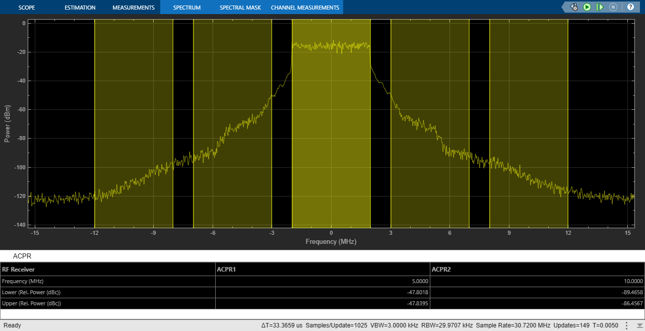
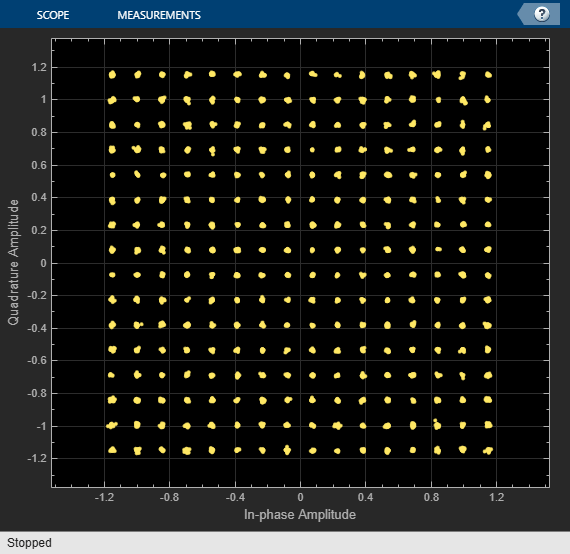
When there is no LTE interference, the ACLR values are around 50 and 87 dB and the overall EVM is around 0.9%.
With LTE interference (Interferer gain = 1). To activate the LTE interference, set the Gain parameter of the Interferer Gain block to a value different from 0. For example, choose 1.
set_param([modelName '/Interferer Gain'],'Gain','1');
sim(modelName);
EVM stats for BWP idx : 1
PDSCH RMS EVM, Peak EVM, slot 0: 1.954 7.974%
DM-RS RMS EVM, Peak EVM, slot 0: 1.570 3.182%
PDSCH RMS EVM, Peak EVM, slot 1: 2.019 6.316%
DM-RS RMS EVM, Peak EVM, slot 1: 1.293 2.529%
Averaged overall PDSCH RMS EVM: 1.987%
Overall PDSCH Peak EVM = 7.9741%
EVM stats for BWP idx : 1
PDSCH RMS EVM, Peak EVM, slot 2: 1.828 5.119%
DM-RS RMS EVM, Peak EVM, slot 2: 1.348 3.909%
PDSCH RMS EVM, Peak EVM, slot 3: 2.086 6.526%
DM-RS RMS EVM, Peak EVM, slot 3: 1.433 4.032%
Averaged overall PDSCH RMS EVM: 1.961%
Overall PDSCH Peak EVM = 6.5257%
EVM stats for BWP idx : 1
PDSCH RMS EVM, Peak EVM, slot 4: 1.944 5.621%
DM-RS RMS EVM, Peak EVM, slot 4: 1.542 3.768%
PDSCH RMS EVM, Peak EVM, slot 5: 2.019 6.000%
DM-RS RMS EVM, Peak EVM, slot 5: 1.519 3.747%
Averaged overall PDSCH RMS EVM: 1.982%
Overall PDSCH Peak EVM = 6.0003%
EVM stats for BWP idx : 1
PDSCH RMS EVM, Peak EVM, slot 6: 1.861 5.701%
DM-RS RMS EVM, Peak EVM, slot 6: 1.578 3.289%
PDSCH RMS EVM, Peak EVM, slot 7: 1.951 7.318%
DM-RS RMS EVM, Peak EVM, slot 7: 1.438 4.102%
Averaged overall PDSCH RMS EVM: 1.906%
Overall PDSCH Peak EVM = 7.3185%
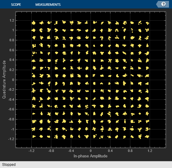
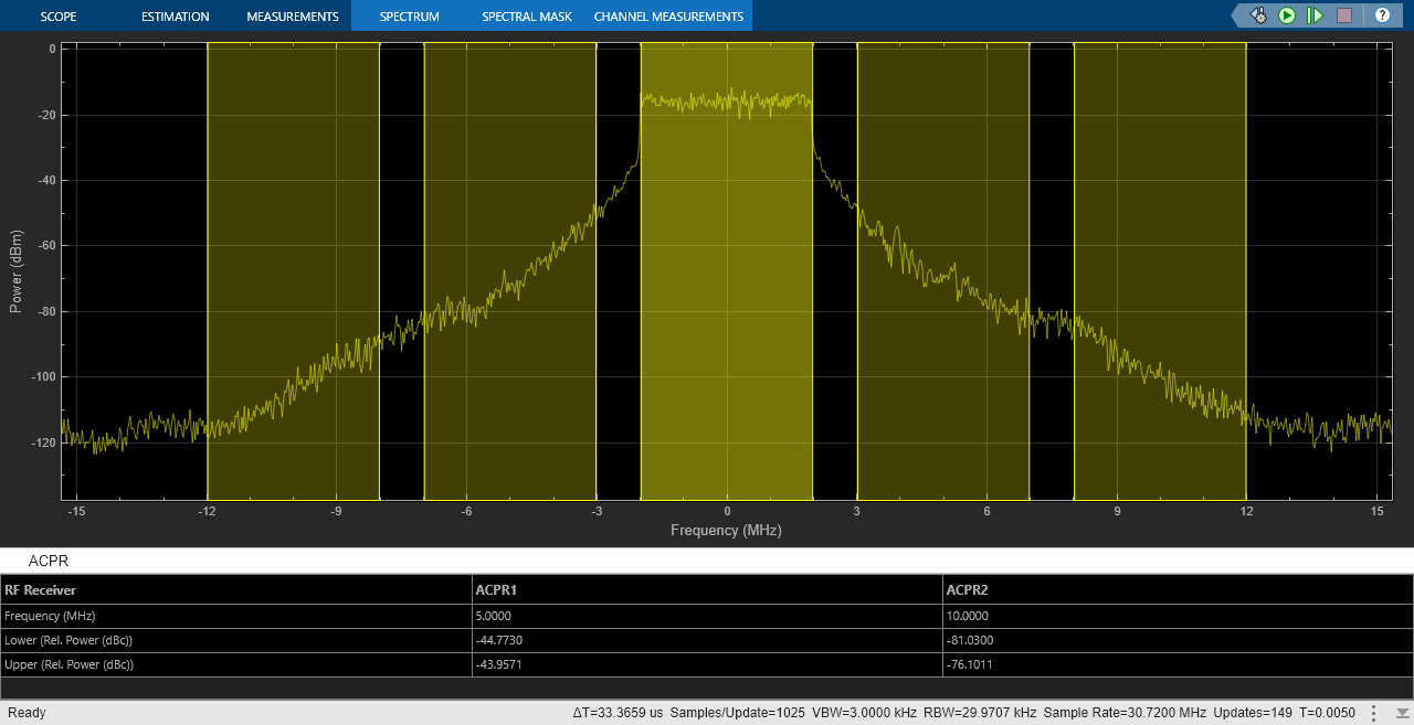
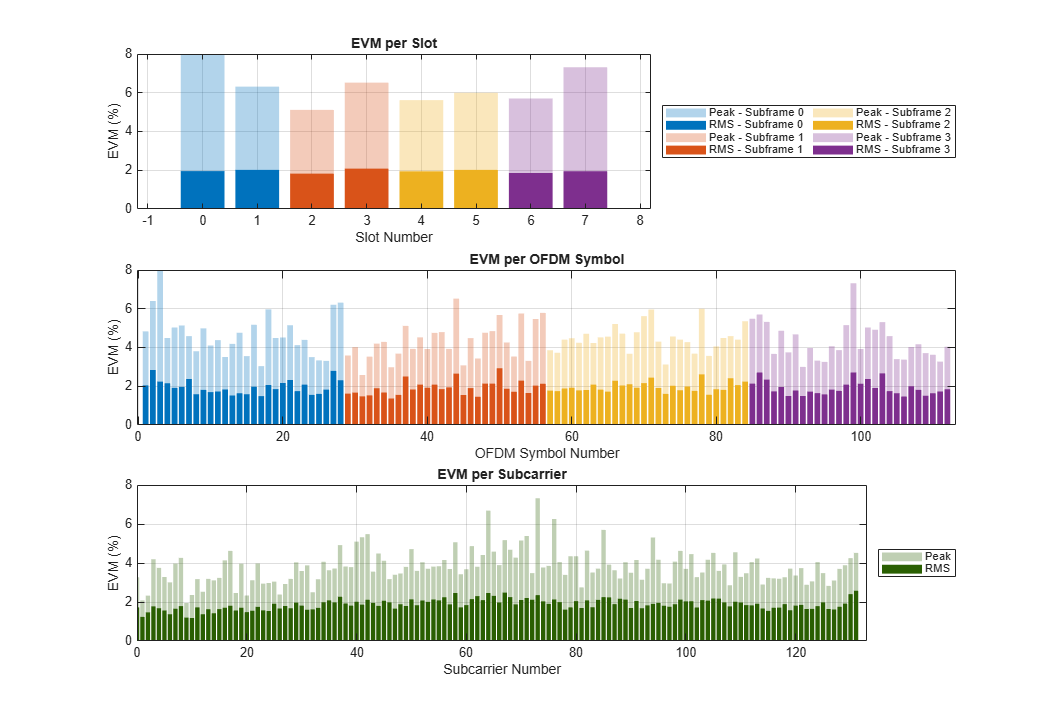
Compared to the previous case, the constellation diagram is more distorted and the spectral regrowth is higher. In terms of the measurements, the ACLR values are around 46 and 82 dB and the overall EVM is around 2%.
The RF Receiver is configured to work with the waveform configurations selected in the 5G NR Test Model and the LTE Test Model blocks and with the NR and LTE carriers centered at 2190 MHz and 2120 MHz, respectively. These carriers are within the NR operating band n65, TS 38.101-1, and the E-UTRA operating band 1, TS 36.101.
Summary and Further Exploration
This example demonstrates how to model and test the reception of an NR waveform when coexisting with an LTE waveform. The RF receiver consists of bandpass filters, amplifiers and a demodulator. To evaluate the impact of the LTE interference, the example modifies the gain of the LTE waveform and performs ACLR and EVM measurements. You can explore the impact of altering the RF impairments as well. For example:
Increase the phase noise by using Phase noise offset (Hz) and Phase noise level (dBc/Hz) parameters on the Demodulator tab of the RF Receiver Subsystem block.
Reduce the input back-off of the Amplifier block by increasing the Gain (dB) parameter on the LNA tab of the RF Receiver Subsystem block.
If you modify the carrier frequencies of the RF Receiver Subsystem block or the NR-TM and E-TM configurations, check if you need to update the parameters of the RF Receiver components as these parameters have been selected to work for the current example configuration. For instance, a change in the carrier frequency requires revising the Passband frequencies and Stopband frequencies parameters of the RF Bandpass Filter block inside the RF Receiver. If you select a bandwidth wider than 20 MHz, check if you need to update the Impulse response duration and Phase noise frequency offset (Hz) parameters of the Demodulator (RF Blockset) block. The phase noise offset determines the lower limit of the impulse response duration. If the phase noise frequency offset resolution is high for a given impulse response duration, a warning message appears, specifying the minimum duration suitable for the required resolution.
You can use this example as the basis for testing the coexistence between NR-TM and E-TM waveforms for different RF configurations. You can try replacing the RF Receiver Subsystem block by another RF subsystem and then configure the model accordingly.
To use a different NR-TM waveform, open the 5G Waveform Generator app, select the NR-TM configuration, and export a new block. Similarly, to use a different E-TM waveform, open the LTE Waveform Generator app, select the E-TM configuration, and export a new block. For more information on how to generate and use such blocks, see Generate Wireless Waveform in Simulink Using App-Generated Block.
References
3GPP TS 38.141-1. "NR; Base Station (BS) conformance testing Part 1: Conducted conformance testing." 3rd Generation Partnership Project; Technical Specification Group Radio Access Network.
3GPP TS 36.141 "E-UTRA; Base Station (BS) conformance testing" 3rd Generation Partnership Project; Technical Specification Group Radio Access Network.
3GPP TS 38.101-1. "NR; User Equipment (UE) radio transmission and reception." 3rd Generation Partnership Project; Technical Specification Group Radio Access Network.
3GPP TS 36.101. "E-UTRA; User Equipment (UE) radio transmission and reception." 3rd Generation Partnership Project; Technical Specification Group Radio Access Network.