GMSK Demodulator Baseband
Demodulate signal using Gaussian minimum shift keying method and Viterbi algorithm
Libraries:
Communications Toolbox /
Modulation /
Digital Baseband Modulation /
CPM
Description
The GMSK Demodulator Baseband block demodulates an input signal that was modulated using the Gaussian minimum shift keying (GMSK) method. The input to this block is a baseband representation of the modulated signal. For more information about this demodulation and the filtering applied, see Algorithms.
Examples
Demodulate a GMSK-modulated signal impaired by AWGN and compute the bit error rate.
The cm_gmsk_mod_demod model generates random Bernoulli distributed binary data and then applies GMSK modulation to frames data. The GMSK-modulated signal passes through an AWGN channel and then is demodulated by using the GMSK method. The bit error rate is calculated on frames of data.
The Error Rate Calculation block has the receive delay set to the value of the traceback depth used by the GMSK Baseband Demodulator block. The model uses the Find Delay block to confirm the delay equals the value of the traceback depth.

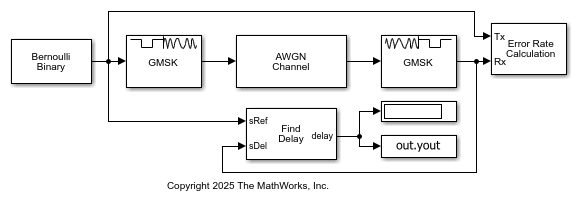
Transmit to receive delay is 16 symbols. BER = 8.3934e-05
Extended Examples
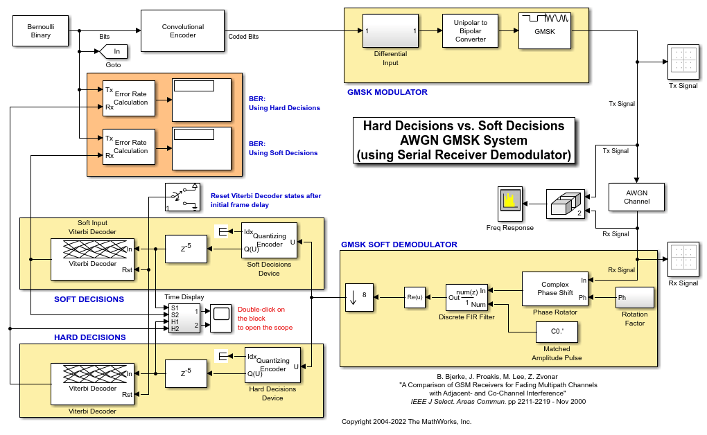
Soft Decision GMSK Demodulator
A system that includes convolutional coding and GMSK modulation. The receiver in this model includes two parallel paths, one that uses soft decisions and another that uses hard decisions. The model computes bit error rates for the two paths to illustrate that the soft decision receiver performs better. The performance advantage for soft decision reception over hard decision reception is expected because soft decisions enable the system to retain more information from the demodulation operation to use in the decoding operation.
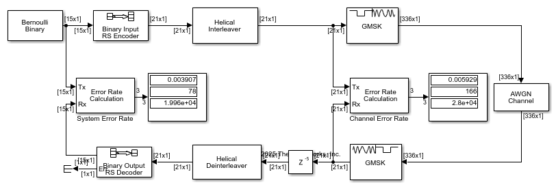
Correct Misalignment of Interleaved Words Due to Demodulation
In communications systems, you can use techniques such as interleaving to protect against burst errors. Interleaving is a process that rearranges the order of data bits or symbols. The effectiveness of interleaving depends on the precise alignment of data words prior to this process. This example shows how to correct for the misalignment of codewords due to delays incurred in digital demodulation, when performing deinterleaving and outer block decoding.
Ports
Input
GMSK-modulated baseband signal, specified as a column vector with a length equal to an integer multiple of the number of Samples per symbol. For information on the processing rates, see Single-Rate Processing and Multirate Processing.
This port in unnamed on the block.
Data Types: double | single
Complex Number Support: Yes
Output
Demodulated output signal, returned as a scalar or column vector. For more information, see Integer-Valued Signals and Binary-Valued Signals and Traceback Depth and Output Delays.
This port is unnamed on the block.
Data Types: double | Boolean | int8 | int16 | int32
Parameters
To edit block parameters interactively, use the Property Inspector. From the Simulink® Toolstrip, on the Simulation tab, in the Prepare gallery, select Property Inspector.
Option to output data as integers or bits, specified as
Integer or Bit.
When you simulate the model, the output is a 1-by-(N /
NSPS) column vector.
N is the length of the input signal, In,
which is the number of input baseband modulated symbols.
NSPS represents the value of
the Samples
per symbol parameter.
When you set this parameter to
Integer, the values output are bipolar (-1or1).When you set this parameter to
Bit, the values output are binary (0or1).
Product of the bandwidth and symbol time of the Gaussian pulse shape, specified as a positive scalar. Use BT product to reduce the bandwidth, at the expense of increased intersymbol interference.
Length of the frequency pulse shape, specified as a positive integer. This parameter represents the truncated frequency pulse length of the Gaussian pulse shape in symbol intervals.
Symbol prehistory, specified as -1,
1, or a vector with elements equal to those values.
This parameter defines the data symbols that the modulator uses before the
block processes symbols, in reverse chronological order.
A scalar value expands to a vector of length LP – 1. LP represents the pulse length, which is specified by the Pulse length (symbol intervals) parameter.
For a vector, the length must be LP – 1.
Initial phase offset of the modulated waveform in radians, specified as a scalar.
Number of samples per input symbol, specified as a positive integer. The number of samples per symbol represents the downsampling factor from input samples to output samples. For more information, see Signal Upsampling and Rate Changes.
Block processing rate, specified as one of these options:
Enforce single-rate processing— The input and output signals have the same port sample time. The block implements the rate change by making a size change at the output when compared to the input. The output width is the number of symbols (which is given by dividing the input length by the Samples per symbol parameter value when the Output type parameter is set toInteger).Allow multirate processing— The input and output signals have different port sample times. The output period is the same as the symbol period and equals the product of the input period and the Samples per symbol parameter value.
Traceback depth for the Viterbi algorithm, specified as a positive integer. The traceback depth specifies the number of trellis branches that the Viterbi algorithm uses to construct each traceback path. The value of this parameter is also the output delay and the number of zero symbols that precede the first meaningful demodulated symbol in the output. For more information, see Traceback Depth and Output Delays.
Output data type, specified as double,
boolean, int8,
int16, or int32.
When you set the Output type parameter to
false, you can set the output to double-precision or signed-integer data types.When you set the Output type parameter to
true, you can set the output to double-precision, signed-integer, or logical data types.
Block Characteristics
Data Types |
|
Multidimensional Signals |
|
Variable-Size Signals |
|
More About
This block accepts a scalar or column vector input signal with a data type of
single or double.
If you set the Output type parameter to
Integer, then the block produces bipolar values of–1and1.If you set the Output type parameter to
Bit, then the block produces binary values of 0 and 1.
In single-rate processing mode, the input and output signals have the same port sample time. The block implicitly implements the rate change by making a size change at the output when compared to the input. The input width must be an integer multiple of the Samples per symbol parameter value, and the input can be a column vector. For a column vector input signal, the width of the input equals the product of the number of symbols and the value for the Samples per symbol parameter.
In multirate processing mode, the input and output signals have different port sample times. The input must be a scalar. The output symbol time is the product of the input sample time and the Samples per symbol parameter value.
Internally, this block creates a trellis description of the modulation scheme and uses the Viterbi algorithm. The Traceback depth parameter, D, in this block is the number of trellis branches used to construct each traceback path. D influences the output delay, which is the number of zero symbols that precede the first meaningful demodulated value in the output.
When you set the Rate options parameter to
Allow multirate processing, and the model uses a variable-step solver or a fixed-step solver with the Tasking Mode parameter set toSingleTasking, then the delay consists of D+1 zero symbols.When you set the Rate options parameter to
Enforce single-rate processing, then the delay consists of D zero symbols.
The optimal Traceback depth parameter value depends on minimum squared Euclidean distance calculations. Alternatively, a typical value, depending on the number of states, can be chosen using the five-times-the-constraint-length rule, which corresponds to 5log2(numStates). The number of states is determined by the following equation:
where:
h = m/p is the modulation index in proper rational form.
m = numerator of modulation index
p = denominator of modulation index
L is the pulse length
Algorithms
The demodulator uses a trellis representation of GMSK and applies a Gaussian Pulse Shaping Filter. It offers demodulation by hard decision. The demodulator generates hard decisions (0s and 1s) using the Viterbi algorithm. The Viterbi algorithm finds the most likely sequence, and instead of maximizing the likelihood function for each bit, it estimates several bits at once as described in [1].
These equations define the frequency pulse shape of the Gaussian pulse shaping filter:
Bb represents the bandwidth of the pulse and T is the symbol durations. Q(t) is the complementary cumulative distribution function.
The BT product parameter represents bandwidth multiplied by time. Use this parameter to reduce the bandwidth at the expense of increased intersymbol interference. The Pulse length (symbol intervals) parameter measures the length of the Gaussian pulse shape in symbol intervals.
References
[1] Anderson, John B., Tor Aulin, and Carl-Erik Sundberg. Digital Phase Modulation. New York: Plenum Press, 1986.
Extended Capabilities
C/C++ Code Generation
Generate C and C++ code using Simulink® Coder™.
Version History
Introduced before R2006a
MATLAB Command
You clicked a link that corresponds to this MATLAB command:
Run the command by entering it in the MATLAB Command Window. Web browsers do not support MATLAB commands.
Select a Web Site
Choose a web site to get translated content where available and see local events and offers. Based on your location, we recommend that you select: .
You can also select a web site from the following list
How to Get Best Site Performance
Select the China site (in Chinese or English) for best site performance. Other MathWorks country sites are not optimized for visits from your location.
Americas
- América Latina (Español)
- Canada (English)
- United States (English)
Europe
- Belgium (English)
- Denmark (English)
- Deutschland (Deutsch)
- España (Español)
- Finland (English)
- France (Français)
- Ireland (English)
- Italia (Italiano)
- Luxembourg (English)
- Netherlands (English)
- Norway (English)
- Österreich (Deutsch)
- Portugal (English)
- Sweden (English)
- Switzerland
- United Kingdom (English)

