Check bug reports for issues and fixes
Software is inherently complex and is not free of errors. The output of a code generator might contain bugs, some of which are not detected by a compiler. MathWorks reports critical known bugs brought to its attention on its Bug Report system at www.mathworks.com/support/bugreports/. Click the "Incorrect Code Generation" filter to obtain a report of known bugs that produce code that might compile and execute, but still produce wrong answers. To save the filtered results, click Save Search.
The bug reports are an integral part of the documentation for each release. Examine periodically all bug reports for a release, as such reports may identify inconsistencies between the actual behavior of a release you are using and the behavior described in this documentation.
In addition to reviewing bug reports, you should implement a verification and validation strategy to identify potential bugs in your design, code, and tools.
Known Bugs for Incorrect Code Generation
All Known Bugs for This Product
Eliminate duplicate code by reusing single static functions in MATLAB Function blocks
Starting in R2023b, the code generator eliminates redundant code by reusing identical static functions generated for each MATLAB Function block in a model. Eliminating redundant code reduces code complexity, reduces memory usage at run time, and improves code readability. Previously, the code generator produced separate functions, resulting in duplication, despite having identical implementations and sharing the same external MATLAB® file.
Consider the model ReuseCodeForMLFB, which includes two MATLAB
Function blocks mfcn1 and mfcn2 that call
the function multi_two. Set the model configuration parameter
Shared code placement to either Auto or
Shared Location. The associated global data store stores the
input of the model.
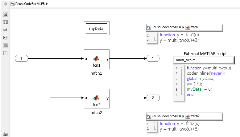
The table compares the code generated in R2023a and R2023b for the model
ReuseCodeForMLFB. In R2023a, the code contains duplicate functions
ReuseCodeForMLFB_multi_two and
ReuseCodeForMLFB_multi_two_f to represent the calls to
multi_two from mfcn1 and mfcn2.
In R2023b, the code reuses the function ReuseCodeForMLFB_multi_two, thus
removing code redundancy.
| Generated Code in R2023a | Generated Code in R2023b |
|---|---|
/* Real-time model */
static RT_MODEL_ReuseCodeForMLFB_T ReuseCodeForMLFB_M_;
RT_MODEL_ReuseCodeForMLFB_T *const ReuseCodeForMLFB_M = &ReuseCodeForMLFB_M_;
static void fcn1(void);
static void fcn2(void);
/* Forward declaration for local functions */
static real_T ReuseCodeForMLFB_multi_two(real_T u);
/* Forward declaration for local functions */
static real_T ReuseCodeForMLFB_multi_two_f(real_T u);
/* Function for MATLAB Function: '<Root>/mfcn1' */
static real_T ReuseCodeForMLFB_multi_two(real_T u)
{
real_T y;
y = 2.0 * u;
myData = u;
return y;
}
/* Output and update for atomic system: '<Root>/mfcn1' */
static void fcn1(void)
{
/* Outport: '<Root>/Out1' incorporates:
* Inport: '<Root>/In1'
*/
ReuseCodeForMLFB_Y.Out1 = ReuseCodeForMLFB_multi_two(ReuseCodeForMLFB_U.In1) +
3.0;
}
/* Function for MATLAB Function: '<Root>/mfcn2' */
static real_T ReuseCodeForMLFB_multi_two_f(real_T u)
{
real_T y;
y = 2.0 * u;
myData = u;
return y;
}
/* Output and update for atomic system: '<Root>/mfcn2' */
static void fcn2(void)
{
/* Outport: '<Root>/Out2' incorporates:
* Inport: '<Root>/In1'
*/
ReuseCodeForMLFB_Y.Out2 = ReuseCodeForMLFB_multi_two_f(ReuseCodeForMLFB_U.In1)
+ 5.0;
}
/* Model step function */
void ReuseCodeForMLFB_step(void)
{
/* MATLAB Function: '<Root>/mfcn1' */
fcn1();
/* MATLAB Function: '<Root>/mfcn2' */
fcn2();
} |
/* Real-time model */
static RT_MODEL_ReuseCodeForMLFB_T ReuseCodeForMLFB_M_;
RT_MODEL_ReuseCodeForMLFB_T *const ReuseCodeForMLFB_M = &ReuseCodeForMLFB_M_;
/* Exported functions */
extern real_T ReuseCodeForMLFB_multi_two(real_T u);
static void fcn1(void);
static void fcn2(void);
/* Function for MATLAB Function: '<Root>/mfcn1' */
real_T ReuseCodeForMLFB_multi_two(real_T u)
{
real_T y;
y = 2.0 * u;
myData = u;
return y;
}
/* Output and update for atomic system: '<Root>/mfcn1' */
static void fcn1(void)
{
/* Outport: '<Root>/Out1' incorporates:
* Inport: '<Root>/In1'
*/
ReuseCodeForMLFB_Y.Out1 = ReuseCodeForMLFB_multi_two(ReuseCodeForMLFB_U.In1) + 3.0;
}
/* Output and update for atomic system: '<Root>/mfcn2' */
static void fcn2(void)
{
/* Outport: '<Root>/Out2' incorporates:
* Inport: '<Root>/In1'
*/
ReuseCodeForMLFB_Y.Out2 = ReuseCodeForMLFB_multi_two(ReuseCodeForMLFB_U.In1) + 5.0;
}
/* Model step function */
void ReuseCodeForMLFB_step(void)
{
/* MATLAB Function: '<Root>/mfcn1' */
fcn1();
/* MATLAB Function: '<Root>/mfcn2' */
fcn2();
} |
Stack size includes input arguments and return value in static code metrics report
Starting in R2023b, the static code metrics report includes the sizes of function input arguments and the return value, in addition to the nonstatic local variables, to measure the function stack size. You can see the increase in the estimated stack size in the Accumulated Stack Size (bytes) and Self Stack Size (bytes) columns of the static code metrics report.
Prior to R2023b, only the nonstatic local variables were considered when measuring the function stack size. The static code metrics assumed that the compiler optimized the function arguments to register memory. So, the sizes of these arguments were not included when calculating the function stack size.
For more information, see Generating a Static Code Metrics Report for Code Generated from MATLAB Code.
Code generation support for concurrent execution of message blocks operating at different rates within a model
Starting in R2023b, Embedded Coder® supports code generation for concurrent execution of message blocks that run at different rates within a model.
To model this in Simulink®, you must configure the model by setting the configuration parameter Allow tasks to execute concurrently on target under Tasking and sample time options in the Solver pane. Simulink allows each rate in the model to execute as an independent concurrent task on the target processor.
The generated code uses a mutex to ensure thread safety. You can replace the default mutex implementations with user-authored functions by using the code replacement library. For more information about code replacement, see Semaphore and Mutex Function Replacement.
Branching and merging root-level ports in export-function models
When concurrent data access is a concern, branching root-level input ports and merging root-level output ports are limited to specific scenarios. Starting in R2023b, you can safely branch and merge root-level ports in more scenarios than previously. The scenarios, both before and now, apply only to export-function models.
Before R2023b, you could safely perform these actions:
Branch root-level input ports configured to use the outside-execution data communication method.
Merge nonscalar root-level output ports configured to use the outside-execution data communication method.
Starting in R2023b, you can also safely perform these actions:
Branch root-level input ports configured to use the during-execution data communication method.
Merge scalar root-level output ports configured to use the outside-execution data communication method.
Merge root-level output ports configured to use the during-execution data communication method.
Note
When concurrent data access is a concern:
Do not design the model to be rate-based.
Do not branch or merge root-level ports configured to use the direct-access data communication method.
Do not merge virtual root-level output ports.
For more information see:
MISRA check to identify variant blocks that do not have a default choice
This table lists the new check that has been introduced under MISRA C™:2012 Coding Standards checks. It checks for variant blocks with startup
variant activation time that do not have a default choice when the Casting
modes is set to Standards Compliant. Refer Casting modes for
further information.
| Model Advisor Check | Check ID |
|---|---|
| Check for variant blocks that do not have a default choice (Simulink Check) | mathworks.misra.DefaultChoiceVariantChecks |
Update guidelines about the creation of data copies for component deployment
Starting in R2023b, the information in these code generation modeling guidelines is modified or removed.
| Modeling Guideline | Description |
| cgsl_0204: Vector and bus signals crossing into atomic subsystems or Model blocks | Removed information about the creation of data copies. |
| cgsl_0402: Signal interfaces for component deployment | Added information about the creation of data copies when the signal type is In Bus Element or Out Bus Element. |
Define file packaging for generated entry-point functions
Starting in R2023b, you can define custom filenames for entry-point functions generated from a model. Use custom filenames to group related functions together in generated code.
In the Embedded Coder Dictionary, under Function Customization Templates, use the Header File and Definition File properties to define filenames for a function customization template. Use the Code Mappings Editor to map functions to the template.
For more information, see Control File Packaging of Generated Entry-Point Functions and Simulink Functions and Define Service Interfaces, Storage Classes, Memory Sections, and Function Templates for Software Architecture.
Define service interface configurations programmatically by using new programming interface
Create and configure a service interface configuration programmatically by using the new programming interface for service interfaces and the existing Embedded Coder Dictionary programming interface, which now supports service interface configurations. The programmatic interface enables you to define service interfaces in an Embedded Coder Dictionary by using a script.
These classes and functions include new behavior that supports service interface definitions.
| Class | New behavior in R2023b |
|---|---|
coder.Dictionary |
|
coder.dictionary.Section |
|
coder.dictionary.Entry |
|
| Function | New behavior in R2023b |
|---|---|
coder.dictionary.copy | Copy definitions from one service interface configuration to another service interface configuration. |
coder.dictionary.move | Move definitions between two service interface configurations. |
coder.dictionary.create | Create a service interface configuration. |
For more information, see Create Service Interface Configuration Programmatically.
Timer service interface support for custom blocks that use time values
Before R2023b, if a model included an inlined S-Function block for a C MEX S-function that relied on time values and the model was configured to use a service code interface, the code generator returned an error.
Starting in R2023b, you can implement inlined S-Function blocks for C MEX S-functions that access 32-bit time values and use these blocks in models configured to use timer service interfaces. You inline an S-Function block by associating the block with a target file. The target file calls Target Language Library (TLC) library functions, which set up communication with Simulink and provide the code generator with specifications for generating code for the block. To generate timer service interface code, the code generator requires the target file to use the enhanced TLC interface, which enables block function optimizations.
For more information, see:
Bitfield storage class support for fixed-point and integer data
types
Previously, you could use the Bitfield storage class to generate a
structure that stores Boolean data in named bit fields. In R2023b, you can reduce
memory usage by using the Bitfield storage class to store
fixed-point and integer data in named bit fields. The size of the fixed-point or
integer type must not be greater than the size of a native integer type.
For more information, see Choose Storage Class for Controlling Data Representation in Generated Code.
Open example models from the documentation or command line
Use openExample
to open example models from the command line. For example, to open the
CodeBuildModel model,
enter:
openExample('CodeBuildModel')You can also find and open models by using the function modelfinder
and by using the documentation, including the examples in this table. This table shows
example models that have been renamed in R2023b.
For more information, see Open code generation example models from the documentation or command line.
Enhanced support for stop conditions in C++11 example main
In R2023b, Embedded Coder adds code generation support for conditional stops in example
ert_main.cpp for models configured for the C++11 language standard.
An example of stop conditions now supported includes using a Stop Simulation
block in your model.
Avoid MISRA violations by initializing local variables to zero in generated code
Before R2023b, the code generator did not initialize local variables to zero. For example, see this code snippet.
/* Model step function */
void LocalDataInitializationExample_step(void)
{
real_T rtb_Gain4;
real_T rtb_Sum1;You can now generate code that initializes local variables to zero by clearing the new model configuration parameter Remove local variable initialization to zero value. This parameter is selected by default.
Explicitly initialize local variables to zero to avoid generating code that contains violations of MISRA C++:2008 Rule 0-1-4 (Polyspace Bug Finder) and to comply with other necessary coding standards.
For example, see this code snippet.
/* Model step function */
void LocalDataInitializationExample_step(void)
{
real_T rtb_Gain4 = 0.0;
real_T rtb_Sum1 = 0.0;For more information, see Control Generation of Initialization Code for Local Variables Set to Zero.
Support for multiple uses of $N and $R naming
rule tokens for memory sections
Before R2023b, an identifier naming rule for a memory section could not contain more
than one instance each of the $N and $R naming
rule tokens. You can now use these naming rule tokens multiple times within a memory
section naming rule. Use multiple instances of these tokens to name memory sections
in a way that is consistent with AUTOSAR rules.
For more information about naming rule tokens, see Identifier Format Control.
Quick Start presents relevant next steps based on your modeling style and code generation goals
When you prepare your model for code generation by using Embedded Coder Quick Start, the tool presents relevant next steps based on these criteria of your modeling style and code generation goals:
Export-function or rate-based model
Top model or subsystem build
Single-instance or multi-instance code
The next steps can include opening the code generation report, opening the SIL/PIL Manager app, or exploring examples that show how to further customize the generated code. For more information, see Generate Code by Using the Quick Start Tool.
Speed up generated code execution with Halide
In R2023b, the code generator supports code generation for Halide, a programming language designed for fast and efficient computation on images and tensors. You can generate Halide code from Simulink models by using the new model configuration parameter Generate Halide code.
You can generate Halide code for these blocks in a Simulink model:
MATLAB Function with the matrix multiplication (*) operation
In R2023b, the code generator supports Halide code generation only when the
Hardware board parameter is set to
None.
For computationally intensive operations such as cascaded matrix multiplication, Halide can significantly improve the execution speed of the generated code. For more information, see Speed Up Generated Code Execution with Halide Code.
Stack size includes input arguments and return value in static code metrics report
Starting in R2023b, the static code metrics report includes the sizes of function input arguments and the return value in addition to the non-static local variables to measure the function stack size. You can see the increase in the estimated stack size in the static code metrics report in the Accumulated Stack Size (bytes) and Self Stack Size (bytes) columns.
Prior to R2023b, only the non-static local variables were considered to measure the function stack size. This is because the static code metrics assumed that the compiler could optimize the function arguments to register memory and was not included to calculate the function stack size.
For more information, see Generate Static Code Metrics Report for Simulink Model.
Use of C99 data types in generated service interface
When you specify a file that contains a service interface configuration for the Shared coder dictionary configuration parameter, the software sets the Data type replacement configuration parameter to Use C data types with fixed-width integers. The code generator creates a service interface that uses C99 data types.
For more information, see:
Enhancements for code generation with C99 data types
When you set Data type replacement to Use C data types
with fixed-width integers:
The Specify custom data type names
(EnableUserReplacementTypes) configuration parameter is
supported. Instead of generating the C99 data type names and limit identifiers,
you can specify custom names and custom limit identifiers.
The word size values for target and production integer data types do not need to include the values 8 and 16 bits. In addition, a word size value can be a value other than 8, 16, 32, or 64 bits.
You can run external mode simulations by using XCP, TCP/IP, or serial communication.
For more information, see Manage Replacement of Simulink Data Types in Generated Code.
Functionality being removed or changed
crossReleaseImport supports only last eight releases
crossReleaseImport supports the import of generated code from only the
previous eight releases. For example, in R2023b, you can use
crossReleaseImport to import code generated only by releases R2019b
to R2023a.
For more information, see Cross-Release Code Integration and crossReleaseImport.
Deploy AUTOSAR Adaptive Architecture Models Using Embedded Coder Support Package for Service-Oriented Applications on Linux
In R2023b the Embedded Coder Support Package for Service-Oriented Applications on Linux® has added the following enhancements:
You can deploy AUTOSAR Adaptive architecture models.
You can deploy and calibrate AUTOSAR adaptive applications on WSL (Windows® Subsystem for Linux) over Windows machine as target.
For more information, see Build Simulink Model and Deploy Application.
Introduction to Custom Hardware App
Starting in R2023b, Custom Hardware App supports the Linux Runtime Manager External Mode workflow. DDS Blockset models and Adaptive AUTOSAR models configured for external mode gets access to the custom hardware app. Use the app to deploy applications on target and perform external mode simulation by using the buttons provided in hardware tab in the toolstrip. Use the Linux Runtime Manager tool to setup and connect to a target.
Customize Groups in ASAP2 File
Starting in R2023b, Embedded Coder allows you to customize groups in ASAP2 file. This feature allows you to add, delete, modify, find, filter, and fetch groups by using the ASAP2 programming interface. For more information, see Export Characteristic and Measurement Objects in Groups.
Functionality being removed or changed
In R2023b, linuxRuntimeManager function replaces the existing
linux.RuntimeManager.open function which is used to open the Linux
Runtime Manager. For more information, see Linux Runtime Manager.
Starting from R2023b, the Generate Calibration Files tool for Embedded Coder allows you to generate separate ASAP2 files for compu methods and record layouts for component models. For more information, see coder.asap2.export function.
lcc-win64 compiler will be removed
Warns
The lcc-win64 compiler will be removed in a future release. For information
about supported compilers, see Supported and Compatible Compilers - Windows.
Aggregation of code profiling results and identification of worst-case execution
Use a coder.profile.ExecutionTimeSet or coder.profile.ExecutionStackSet object to aggregate execution-time or stack
usage profiles, respectively, from multiple software-in-the-loop (SIL),
processor-in-the-loop (PIL), or XCP-based external mode simulations of a model. Then, using
the Code Profile Analyzer, identify the most demanding execution and test for each task and
view the corresponding code or model path.
For more information, see Aggregate Execution-Time Profiles to Identify Worst Execution and Aggregate Stack Usage Profiles and Identify Most Demanding Task Execution.
Generate SIMD code for complex data types
In R2023b, you can generate SIMD code for operations on complex data types that have
single or double base types. For computationally
intensive operations on supported blocks, SIMD intrinsics can significantly improve the
performance of the generated code on Intel® platforms. To generate SIMD code, specify an instruction set to use by setting
the model configuration parameter Leverage target hardware instruction set
extensions and optionally selecting the Optimize
reductions parameter. For more information, see Generate SIMD Code from Simulink Blocks and Optimize Code for Reduction Operations by Using SIMD.
Improved code efficiency and better integration of inlined S-Functions
Starting in R2023b, the enhanced TLC block interface more effectively integrates code for S-Function blocks into the generated code of the model as compared to the existing TLC block interface. This improved integration significantly enhances the code quality and offers these benefits:
Improved buffer allocation for the inputs and outputs of S-Function blocks in the generated code
Improved inlining of the code generated for the S-Function block
Reuse of local variables used in for-loop iterations
A more explicit set of cross-release compatible TLC library functions
For example, consider the model mtimestwo that includes two identical
S-Function blocks.

In this case, the TLC for these S-Functions is expressed as:
%function Outputs(block, system) Output
/* Multiply input by two start */
%assign rollVars = ["U", "Y"]
%assign paramVal = (1 == block.SFcnParamSettings.GenUncompilableCode) ? "2_0" : "2.0"
%roll idx = RollRegions, lcv = RollThreshold, block, "Roller", rollVars
%<LibBlockOutputSignal(0, "", lcv, idx)> = \
%<LibBlockInputSignal(0, "", lcv, idx)> * %<paramVal>;
%endroll
/* Multiply input by two end */
%endfunctionThis table compares the code generated with the TLC block interface and the enhanced TLC block interface.
The generated code with the enhanced TLC block interface eliminates the redundant temporary
variable i1 and data copies u0 and y0.
It also eliminates unnecessary creation of local scope for S-Function
blocks.
| Code with TLC block interface | Code with enhanced TLC block interface |
|---|---|
void mTLC_timestwo_demo_step(void)
{
real_T rtb_Gain[10];
int32_T i;
for (i = 0; i < 10; i++) {
/* Outport: '<Root>/Out1' incorporates:
* Gain: '<S1>/Gain'
* Inport: '<Root>/In1'
*/
mTLC_timestwo_demo_Y.Out1[i] = 5.0 * mTLC_timestwo_demo_U.In1[i];
}
/* S-Function (sfcn_timestwo_v3): '<S1>/S-Function' incorporates:
* Outport: '<Root>/Out1'
*/
/* Multiply input by two start */
{
int_T i1;
const real_T *u0 = &mTLC_timestwo_demo_Y.Out1[0];
real_T *y0 = &rtb_Gain[0];
for (i1=0; i1 < 10; i1++) {
y0[i1] = u0[i1] * 2.0;
}
}
/* Multiply input by two end */
/* Gain: '<S2>/Gain' */
for (i = 0; i < 10; i++) {
rtb_Gain[i] *= 10.5;
}
/* End of Gain: '<S2>/Gain' */
/* S-Function (sfcn_timestwo_v3): '<S2>/S-Function' incorporates:
* Outport: '<Root>/Out1'
*/
/* Multiply input by two start */
{
int_T i1;
const real_T *u0 = &rtb_Gain[0];
real_T *y0 = &mTLC_timestwo_demo_Y.Out1[0];
for (i1=0; i1 < 10; i1++) {
y0[i1] = u0[i1] * 2.0;
}
}
/* Multiply input by two end */
} |
void mTLC_timestwo_demo_step(void)
{
real_T rtb_Gain[10];
int32_T i;
for (i = 0; i < 10; i++) {
/* Outport: '<Root>/Out1' incorporates:
* Gain: '<S1>/Gain'
* Inport: '<Root>/In1'
*/
mTLC_timestwo_demo_Y.Out1[i] = 5.0 * mTLC_timestwo_demo_U.In1[i];
}
/* S-Function (sfcn_timestwo_v3): '<S1>/S-Function' incorporates:
* Outport: '<Root>/Out1'
*/
/* Multiply input by two start */
for (i = 0; i < 10; i++) {
rtb_Gain[i] = mTLC_timestwo_demo_Y.Out1[i] * 2.0;
}
/* Multiply input by two end */
/* Gain: '<S2>/Gain' */
for (i = 0; i < 10; i++) {
rtb_Gain[i] *= 10.5;
}
/* End of Gain: '<S2>/Gain' */
/* S-Function (sfcn_timestwo_v3): '<S2>/S-Function' incorporates:
* Outport: '<Root>/Out1'
*/
/* Multiply input by two start */
for (i = 0; i < 10; i++) {
mTLC_timestwo_demo_Y.Out1[i] = rtb_Gain[i] * 2.0;
}
/* Multiply input by two end */
} |
For more information, see Improve Code Efficiency and Integration of Inlined S-Functions.
Code Profile Analyzer improvements
Use the enhanced Code Profile Analyzer to analyze memory usage and execution-time metrics from software-in-the-loop (SIL), processor-in-the-loop (PIL), or XCP-based external mode simulations. In R2023b, you can:
Generate PDF reports from the metrics produced by the simulations.
Show function-call stack memory usage for specific steps of SIL and PIL simulations.
For more information, see View and Compare Code Execution Times and Stack Usage Profiling for Code Generated from Simulink Models.
C++ code profiling for XCP external mode simulations
You can now use XCP-based external mode simulations to perform execution-time profiling of
generated C++ code. In previous releases, the simulations produce an error if you set the
CodeExecutionProfiling configuration parameter to
'on' and the CodeInterfacePackaging configuration
parameter to 'C++ class'.
For more information, see Execution Profiling for Generated Code and Create Execution-Time Profile for Generated Code.
Data copy reduction for Bus Assignment blocks that change the value of a nested bus element
Before R2023b, the generated code contained unnecessary temporary variables and data copies for modeling patterns that used multiple Bus Assignment blocks to change the value of a nested bus element. Starting in R2023b, the code generator does not generate the unnecessary temporary variables and data copies. Instead, the generated code performs inplace updates by reusing the input bus buffers. Eliminating unnecessary temporary variables and data copies reduces RAM consumption and improves code execution speed.
Consider the mBusRouting model in which the bus signal
BusType1 feeds into the Bus Selector and Bus Assignment block
BusAssignment2. The Bus Selector block outputs the nested bus element
field3 and the Bus Assignment1 block changes the value
of the field4 of the field3. Depending on the value of
In3, the Bus Assignment2 block assigns the new values to
the bus element field3 of the input bus signal.
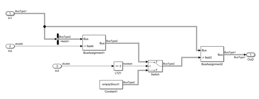
In R2023a, the code generator produced this code:
void mBusRouting_step(void)
{
BusType2 rtb_Switch;
rtb_Switch.field4 = rtU.In2;
if (!(rtU.In3 <= 3.0)) {
memset(&rtb_Switch, 0, sizeof(BusType2));
}
rtY.Out2 = rtU.In1;
rtY.Out2.field3 = rtb_Switch;
}The generated code contained an unnecessary temporary variable rtb_Switch
for holding the updated value before assigning the value to
rtY.Out2.field3.
In R2023b, the code generator produces this code:
void mBusRouting_step(void)
{
rtY.Out2 = rtU.In1;
rtY.Out2.field3.field4 = rtU.In2;
if (!(rtU.In3 <= 3.0)) {
memset(&rtY.Out2.field3, 0, sizeof(BusType2));
}
}The generated code does not contain the temporary variable rtb_Switch for
holding the updated value. The code directly assigns the value to
rtY.Out2.field3. For more information, see Reduce Data Copies for Bus Assignment Blocks in Generated Code.
Data copy reduction for atomic For Each subsystems
Starting in R2023b, the generated code contains fewer data copies for models containing an atomic For Each subsystem whose:
Input and output signals use the Reusable storage class.
Function packaging is set to
inline or Nonreuasable with the
void_void function interface setting.
For Each block has the same dimension specified for the input Partition Dimension and output Concatenation Dimension.
For example, the model mRCSCInForEachSS contains an atomic inlined For Each
subsystem ForEachSS. The input and output signals of
ForEachSS are configured to use the Reusable storage
class through the Code Mappings editor.
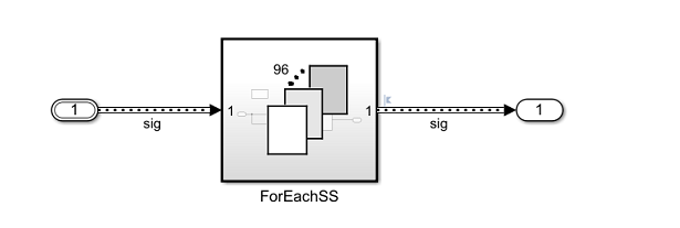
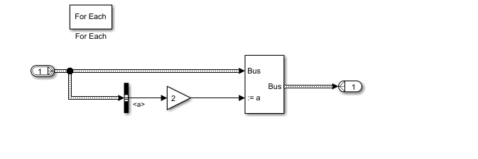
In R2023a, the code generator produced this code:
void mRCSCInForEachSS_step(void)
{
BusObject sig_1_0[96];
int32_T ForEach_itr;
for (ForEach_itr = 0; ForEach_itr < 96; ForEach_itr++) {
sig_1_0[ForEach_itr].a = 2.0 * sig[ForEach_itr].a;
sig_1_0[ForEach_itr].b = sig[ForEach_itr].b;
sig[ForEach_itr] = sig_1_0[ForEach_itr];
}
}The generated code contained the unnecessary temporary array sig_1_0 and
data copies.
In R2023b, the code generator produces this code:
void mRCSCInForEachSS_step(void)
{
int32_T ForEach_itr;
for (ForEach_itr = 0; ForEach_itr < 96; ForEach_itr++) {
sig[ForEach_itr].a = 2.0 * sig[ForEach_itr].a;
}
}
The generated code does not contain the unnecessary temporary array sig_1_0
and data copies. Instead, the code performs inplace updates by reusing the
sig buffers. Reusing the buffers reduces RAM consumption and improves code
execution speed. For more information, see Specify Buffer Reuse for Signals in a Path.
SIMD optimizations for code containing control flow constructs
In R2023b, you can generate SIMD instructions for code that contains control flow constructs, such as blocks containing conditional logic or saturation arithmetic. SIMD code generation is supported for control flow constructs that the code generator can convert to data flow constructs. For some computationally intensive operations, SIMD intrinsics can improve the performance of the generated code on Intel platforms. To generate SIMD code, specify an instruction set to use by setting the model configuration parameter Leverage target hardware instruction set extensions and optionally selecting the Optimize reductions parameter. For more information, see Generate SIMD Code from Simulink Blocks and Optimize Code for Reduction Operations by Using SIMD.
Improved code efficiency for models containing MATLAB System blocks
In R2023b, the code generator may eliminate unnecessary temporary variables and associated data copies, which reduces RAM consumption and improves code execution speed.
Consider the model mCodeMetrics_MLSB with a MATLAB System block.
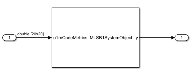
The following compares code generated in R2023a to the code generated in R2023b for the
model. In R2023a, the generated code contains a temporary variable u0 and
redundant data copies of the variable. In R2023b, the temporary variable
u0 and data copies are eliminated.
R2023a Generated Code
void mCodeMetrics_MLSB1_step(void)
{
real_T u0[400];
real_T i;
real_T j;
real_T rtb_MATLABSystem;
boolean_T found;
// MATLABSystem: '<Root>/MATLAB System' incorporates:
// Inport: '<Root>/In4'
std::memcpy(&u0[0], &mCodeMetrics_MLSB1_U.In4[0], 400U * sizeof(real_T));
// Implement algorithm. Calculate y as a function of input u and
// discrete states.
// 'mCodeMetrics_MLSB1SystemObject:32' i = 1;
i = 1.0;
// 'mCodeMetrics_MLSB1SystemObject:33' found = false;
found = false;
// 'mCodeMetrics_MLSB1SystemObject:34' y = 0;
rtb_MATLABSystem = 0.0;
// 'mCodeMetrics_MLSB1SystemObject:35' while (i < size(u1, 1)) && (found == false)
while (i < 20.0 && !found) {
// 'mCodeMetrics_MLSB1SystemObject:36' j = 1;
j = 1.0;
// 'mCodeMetrics_MLSB1SystemObject:37' while (j < size(u1, 2))
while (j < 20.0 && !(u0[(int32_T)i - 1 + 20 * ((int32_T)j - 1)] == 0.0)) {
// 'mCodeMetrics_MLSB1SystemObject:38' if u1(i, j) == 0
// 'mCodeMetrics_MLSB1SystemObject:40' else
// 'mCodeMetrics_MLSB1SystemObject:41' j = j + 1;
j = j + 1.0;
}
// 'mCodeMetrics_MLSB1SystemObject:45' if (j < size(u1, 2))
if (j < 20.0) {
// 'mCodeMetrics_MLSB1SystemObject:46' found = true;
found = true;
// 'mCodeMetrics_MLSB1SystemObject:47' y = i + j*size(u1, 1);
rtb_MATLABSystem = i + j * 20.0;
}
// 'mCodeMetrics_MLSB1SystemObject:49' i = i + 1;
i = i + 1.0;
}
// Outport: '<Root>/Out2'
mCodeMetrics_MLSB1_Y.Out2 = rtb_MATLABSystem;
}R2023b Generated Code
void mCodeMetrics_MLSB1_step(void)
{
real_T i;
real_T j;
real_T rtb_MATLABSystem;
boolean_T found;
// MATLABSystem: '<Root>/MATLAB System'
// Implement algorithm. Calculate y as a function of input u and
// discrete states.
// 'mCodeMetrics_MLSB1SystemObject:32' i = 1;
i = 1.0;
// 'mCodeMetrics_MLSB1SystemObject:33' found = false;
found = false;
// 'mCodeMetrics_MLSB1SystemObject:34' y = 0;
rtb_MATLABSystem = 0.0;
// 'mCodeMetrics_MLSB1SystemObject:35' while (i < size(u1, 1)) && (found == false)
while (i < 20.0 && !found) {
// 'mCodeMetrics_MLSB1SystemObject:36' j = 1;
j = 1.0;
// 'mCodeMetrics_MLSB1SystemObject:37' while (j < size(u1, 2))
while (j < 20.0 && !(mCodeMetrics_MLSB1_U.In4[(int32_T)i - 1 + 20 *
((int32_T)j - 1)] == 0.0)) {
// 'mCodeMetrics_MLSB1SystemObject:38' if u1(i, j) == 0
// 'mCodeMetrics_MLSB1SystemObject:40' else
// 'mCodeMetrics_MLSB1SystemObject:41' j = j + 1;
j = j + 1.0;
}
// 'mCodeMetrics_MLSB1SystemObject:45' if (j < size(u1, 2))
if (j < 20.0) {
// 'mCodeMetrics_MLSB1SystemObject:46' found = true;
found = true;
// 'mCodeMetrics_MLSB1SystemObject:47' y = i + j*size(u1, 1);
rtb_MATLABSystem = i + j * 20.0;
}
// 'mCodeMetrics_MLSB1SystemObject:49' i = i + 1;
i = i + 1.0;
}
Functionality being removed or changed
Code replacement argument objects use code descriptor types system instead of embedded types system
Behavior change in future release
In R2023b, the Type property of code replacement argument objects,
such as RTW.TflArgNumeric and RTW.TflArgMatrix
objects, now uses the code descriptor types system instead of the embedded types system.
For example, a numeric argument that previously had a Type of
embedded.numerictype now has a Type of
coder.descriptor.types.Numeric.
SIL/PIL unit-testing of function-call subsystems
You can use the SIL/PIL Manager to unit-test code generated from function-call subsystems, including AUTOSAR runnables in export-function models. For more information, see:
PIL connectivity for hardware emulators using Target Framework
To run processor-in-the-loop (PIL) simulations on an emulator, you can define the emulator by
using a target.Emulator
object. The simulation uses the object for starting and stopping the emulator. For more
information, see Define Custom Emulator for Target Connectivity.
SIL/PIL data logging for referenced models
For referenced models in a top-model or Model block SIL/PIL simulation, you
can log signals and discrete states. During the simulation, stream the signal and state data
to the Simulation Data Inspector. At the end of the simulation, store logged data in
logsout and xout.
For more information, see SIL/PIL Manager Verification Workflow.
STMicroelectronics STM32 Processors: Support for STMicroelectronics STM32U5xx-based boards
The Embedded Coder Support Package for STMicroelectronics® STM32 Processors now supports the new STM32U5xx-based boards. Starting R2023b, you can:
Generate and build code using an STM32CubeMX project file.
Use the ADC, PWM, GPIO, Hardware Interrupt, Timer, Encoder, I2C, and UART/USART blocks to implement Model-Based Design workflows.
Monitor signals and tune parameters in the external mode.
Run processor-in-the-loop (PIL) simulation in the serial communication mode.
Embedded Coder Support Package for ARM Cortex-A Processors
In R2023b, the Embedded Coder Support Package for ARM® Cortex®-A Processors documentation is included within the Embedded Coder documentation.
To view support package documentation from previous releases, see Archived R2023a Embedded Coder Support Package for ARM Cortex-A Processors documentation.
Embedded Coder Support Package for ARM Cortex-R Processors
In R2023b, the Embedded Coder Support Package for ARM Cortex-R Processors documentation is included within the Embedded Coder documentation.
To view support package documentation from previous releases, see Archived R2023a Embedded Coder Support Package for ARM Cortex-R Processors documentation.
Embedded Coder Support Package for Intel SoC Devices
In R2023b, the Deep Learning HDL Toolbox™ Support Package for Intel FPGA and SoC Devices documentation is included within the Embedded Coder documentation.
To view support package documentation from previous releases, see Archived R2023a Embedded Coder Support Package for Intel SoC Devices documentation.
Embedded Coder Support Package for Xilinx Zynq Platform
In R2023b, the Embedded Coder Support Package for Xilinx® Zynq®-7000 Platform documentation is included within the Embedded Coder documentation.
To view support package documentation from previous releases, see Archived R2023a Embedded Coder Support Package for Xilinx Zynq Platform documentation.
STMicroelectronics STM32 Processors: Support package documentation moved into Embedded Coder documentation
In R2023b, the Embedded Coder Support Package for STMicroelectronics STM32 Processors documentation is included within the Embedded Coder documentation and support package updates are announced in the Embedded Coder release notes.
To view support package documentation from previous releases, see Archived R2023a Embedded Coder Support Package for STMicroelectronics STM32 Processors documentation.
STMicroelectronics STM32 Processors: Support for CORDIC, Comparator, I2S Audio Out, I2S Mic In, and DAC blocks
Starting R2023b, you can use the following blocks with STM32 processor-based boards.
Use the CORDIC block to enable hardware acceleration of trigonometric and hyperbolic mathematical functions.
Use the Comparator block to compare two analog inputs to the peripheral and provide the logical value of the result for STM32G4xx, STM32H7xx, STM32L4xx, and STM32L5xx processor-based boards.
Use the updated I2S Audio Out block to send an audio stream and I2S Mic In block to read an audio stream on STM32F7xx and STM32G4xx processor-based boards.
Use the updated Digital to Analog Converter (DAC) block to receive the digital value and convert it to the equivalent analog voltage on a specified channel in STM32F4xx, STM32F7xx, STM32H7xx, STM32L4xx, and STM32L5xx processor-based boards.
STMicroelectronics STM32 Processors: Establish CAN or FDCAN Communication for STMicroelectronics STM32 Processor Based Boards
The Communication Using CAN or FDCAN Blocks for STMicroelectronics STM32 Processor Based Boards example shows how to use CAN or FDCAN blocks and establish CAN or FDCAN communication protocol on STM32 processor based boards.
Using this example, you can implement the CAN communication protocol in the following modes:
Internal Loopback Mode - Write and read data using CAN/FDCAN Write and CAN/FDCAN Read blocks in internal loopback mode.
Polling Based - Send and receive data from one board to another using polling-based FDCAN protocol.
Interrupt Based - Send and receive data from one board to another using interrupt-based FDCAN protocol.
Interrupt Based and HTS221 Sensor Data - Send more than 8 data bytes at a higher bit rate with Hardware Interrupt block and read temperature and humidity values.
Classic CAN Interrupt Based - Establish communication between FDCAN and CAN peripherals using the classic CAN frame format. Send the humidity and temperature values from the B-L475E-IOT01A2 board upon receiving the remote frame from NUCLEO-L552ZE-Q.
STMicroelectronics STM32 Processors: Support for PIL executions in MATLAB Using STM32 Cube MX
The Embedded Coder Support Package for STMicroelectronics STM32 Processors supports processor-in-the-loop (PIL) executions using STM32 CubeMX to verify the code generated using:
MATLAB Coder™ app
MATLAB functions using MATLAB Coder at the command line.
STMicroelectronics STM32 Processors: Support for ARM GNU Toolchain 11.3.Rel1, CMSIS V5.9.0, and CMSIS-DSP v1.14.3
In R2023b, enhancements to the Embedded Coder Support Package for STMicroelectronics STM32 Processors include:
Support for ARM GNU Toolchain 11.3.Rel1
Support for Cortex Microcontroller Software Interface Standard (CMSIS) v5.9.0. and CMSIS DSP 1.14.3
Modifications to the CMSIS libraries to improve the performance of the code replacement library (CRL)
ARM Cortex-M Processors: Support package documentation moved into Embedded Coder documentation
In R2023b, the Embedded Coder Support Package for ARM Cortex-M Processors documentation is included within the Embedded Coder documentation.
To view support package documentation from previous releases, see Archived R2023a Embedded Coder Support Package for ARM Cortex-M Processors documentation.
ARM Cortex-M Processors: Support for ARM GNU Toolchain 11.3.Rel1, CMSIS V5.9.0, and CMSIS-DSP v1.14.3
In R2023b, enhancements to the Embedded Coder Support Package for ARM Cortex-M Processors include:
Support for ARM GNU Toolchain 11.3.Rel1
Support for Cortex Microcontroller Software Interface Standard (CMSIS) v5.9.0. and CMSIS DSP 1.14.3
Modifications to the CMSIS libraries to improve the performance of the code replacement library (CRL)
ARM Cortex-M Processors: Support for Log() and Exp() Math Functions using ARM Cortex-M CRL
Starting 2023b, you can generate code for the vector exponential and natural logarithm Simulink blocks and MATLAB functions that calls CMSIS-DSP library using ARM Cortex- M CRL.
ARM Cortex-M Processors: Support for addition and subtraction of fixed point inputs using ARM Cortex-M CRL
Starting 2023b, you can generate code that calls the CRL for addition and subtraction of
word lengths 8 and 16 for fixed-point inputs with
different fractional lengths.
Infineon AURIX TC4x Microcontrollers: Support for HighTec 6.1.0 Compiler
Starting 2023b, you can compile and run the code using the HighTec 6.1.0 compiler in Embedded Coder Support Package for Infineon® AURIX™ TC4x Microcontrollers.
Infineon AURIX TC4x Microcontrollers: Support for Monitor and Tune (External Mode) over Serial
Starting 2023b, you can use the support package to monitor signals and tune parameters in the external mode over the serial communication interface.
Infineon AURIX TC4x Microcontrollers: Support for Infineon Low Level Driver (iLLD) 2.0.1.2.11.
Starting 2023b, the Embedded Coder Support Package for Infineon AURIX TC4x Microcontrollers supports the Infineon Low Level Driver (iLLD) 2.0.1.2.11.
Infineon AURIX TC4x Microcontrollers: CRL Support for FFT and IFFT Block Replacement
The code replacement library (CRL) now supports fast Fourier transform (FFT) and inverse fast Fourier transform (IFFT) blocks, which you can use in signal processing algorithms targeting a parallel processing unit (PPU) on the Infineon AURIX TC4x microcontrollers. CRL requires SoC Blockset™ for AMD.