Model and Architecture Design
Generate HDL code with custom synthesis attributes
You can now generate HDL code that contains custom synthesis attributes by setting the
SynthesisAttributes HDL block property. You can set this property on subsystems,
blocks, and block output signals in your model. Synthesis tools use synthesis attributes to
optimize digital circuit designs for performance, area, and power efficiency by applying
tool-specific constraints. These attributes are specific to synthesis tools and are independent
of HDL languages. For more information, see Synthesis Attributes in HDL Code Generation.
For an example, see Use Synthesis Attributes to Map Adders to DSPs on FPGAs.
Generate HDL code without global reset ports from Delay blocks with nonzero initial conditions
Starting in R2026a, when your model contains Delay blocks that have nonzero initial conditions and you enable the Minimize global resets model configuration parameter, the generated HDL code does not insert global reset ports.
When you enable this parameter, HDL Coder™ declares the initial condition values directly in the signal declaration, which eliminates the need for additional reset logic.
Generate DUT ports for structure type tunable parameters
Starting in R2026a, you can group tunable parameters into a structure, pass the structure as a tunable parameter, and generate DUT ports for each field in the structure.
HDL Coder also generates DUT ports for tunable parameters that you add to the model after loading the model. For more information, see Generate DUT Ports for Tunable Parameters.
Generate DUT ports for tunable parameters in FPGA-in-the-loop
When generating an HDL DUT using HDL Workflow Advisor, you can generate HDL ports for tunable parameters. Starting in R2026a, you can verify this generated DUT by using FPGA-in-the-loop (requires HDL Verifier™).
In the workflow, when HDL Workflow Advisor generates the FPGA programming file and FIL block, the block includes an input port for each tunable parameter. A Constant block drives that input. To control the value of the tunable parameter, change the value of the Constant block. For more information, see Generate DUT Ports for Tunable Parameters.
Use Enabled, Triggered, and Resettable Subsystem blocks as the DUT
Starting in R2026a, you can use the Enabled Subsystem, Triggered Subsystem, and Resettable Subsystem blocks as the design under test (DUT) and generate HDL code from these subsystems.
Generate HDL code and set HDL block properties by using the new Simulink context menu
The context menus that appear when you right-click the Simulink® canvas, subsystem, or model elements such as blocks, signal lines, and annotations are changing in R2026a. To add HDL Coder options to the context menu, right-click the model canvas. Point to Select Apps, then click HDL Coder.
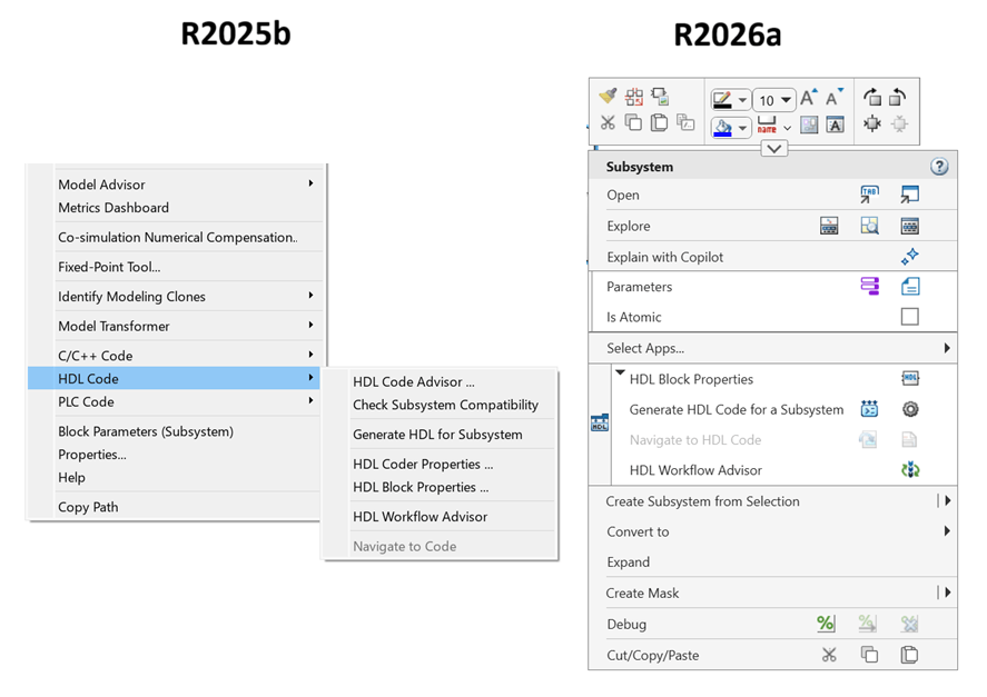
This table lists the buttons available in the HDL Coder section of the new context menu:
| Button | Action |
|---|---|
HDL Block Properties | Opens the HDL Block Properties dialog box. |
Generate HDL Code | Depending on the selection in the Output section of the HDL Code tab in the HDL Coder app, this button generates either HDL code or an IP core:
|
Settings | Opens the models HDL Coder configuration parameter settings. |
Navigate to Code | Navigates to the generated HDL code. |
Open Report | Opens the HDL Code generation report. |
HDL Workflow Advisor | Opens the HDL Workflow Advisor for the selected subsystem. |


You cannot run HDL Code Advisor from the new context menu. To run this tool, open the HDL Coder app. On the HDL Coder tab, in the Assistance section, click Workflow Advisor.
For more information about the new Simulink context menu, see New Simulink context menus prioritize frequently used functionality.
Assign custom names for control signals in multi-rate models
You can now assign custom names to clock, reset, and clock enable control signals for
models that have multiple sample rates. When you set the Clock inputs model configuration parameter to
Multiple in a multi-rate model, you can specify different
names for the control signals by using the Clock input port, Reset input port, and Clock enable input port parameters. In previous releases, you specified a
single name for control signals, which HDL Coder mapped only to the control signals that use the base rate of the model. For
slower rates, HDL Coder generated control signals with names that corresponded to the different rates.
This enhancement allows you to assign signal names to control signals associated with slower
rates in the model.
To specify the custom names for the clock signals for the models that use multiple clocks,
specify the clock names for each rate to the Clock input port model
configuration parameter as elements in a cell array. You can also specify the clock names by
using the hdlset_param function with the
ClockInputPort argument. HDL Coder maps the signal names in the
order from the fastest rate, which is the base rate of the model, to the slowest
rate.
hdlset_param("ModelName","ClockInputPort",{'clk1', 'clk2', 'clk3'})
Naming Style | Clock Settings | Generated HDL Code |
|---|---|---|
Default |
|
ENTITY Subsystem IS
  PORT( clk            :   IN    std_logic;
        clk_1_2        :   IN    std_logic;
        clk_1_4        :   IN    std_logic;
        reset          :   IN    std_logic;
        reset_1_2      :   IN    std_logic;
        reset_1_4      :   IN    std_logic;
        clk_enable     :   IN    std_logic;
        clk_enable_2   :   IN    std_logic;
        clk_enable_4   :   IN    std_logic;
        In1            :   IN    std_logic_vector(15 DOWNTO 0);  -- int16
        Out1           :   OUT   std_logic_vector(15 DOWNTO 0);  -- int16
        );
END Subsystem; |
Custom Names |
|
ENTITY Subsystem IS
  PORT( clk1           :   IN    std_logic;
        clk2           :   IN    std_logic;
        clk3           :   IN    std_logic;
        reset1         :   IN    std_logic;
        reset2         :   IN    std_logic;
        reset3         :   IN    std_logic;
        clk_en1        :   IN    std_logic;
        clk_en2        :   IN    std_logic;
        clk_en3        :   IN    std_logic;
        In1            :   IN    std_logic_vector(15 DOWNTO 0);  -- int16
        Out1           :   OUT   std_logic_vector(15 DOWNTO 0);  -- int16
        );
END Subsystem; |
For more information, see Customize Clock Bundle Names in Generated Code.
Functionality being removed or changed
Code for option on the HDL Code tab now requires a pinned model or subsystem
Behavior change
Starting in R2026a, to generate HDL code or a test bench, or open the HDL
Code Advisor, you must pin a subsystem or model in the HDL
Code tab. Select a subsystem or click the canvas of the top-level model
to select the model and, in the Generate Code section, click the
Remember Selection button  . If you do not pin a subsystem or model, you cannot
use the HDL Code Advisor, Generate HDL Code,
and, if the Code for selection is not a model, Generate
Testbench, buttons in the HDL Code tab.
. If you do not pin a subsystem or model, you cannot
use the HDL Code Advisor, Generate HDL Code,
and, if the Code for selection is not a model, Generate
Testbench, buttons in the HDL Code tab.
For example, in this image the HDL_DUT subsystem is not pinned:

Removal of Check for presence of reals in generated HDL code HDL configuration parameter
Still runs
In the Configuration Parameters dialog box and in the Workflow Advisor app, the
parameter Check for presence of reals in generated HDL code
has been removed. The corresponding command-line configuration property
TreatRealsInGeneratedCodeAs is not removed.
Block Enhancements
Generate HDL code for Complex to Magnitude-Angle block that use fixed-point data types
HDL Coder can now generate HDL code for Complex to Magnitude-Angle blocks that use fixed-point data types. To generate HDL code:
Set the Output parameter to
Magnitude and angle,Magnitude, orAngle.Set the Approximate method parameter to
CORDIC.
For more information, see the HDL Code Generation section in the Complex to Magnitude-Angle block.
Use vector data as inputs for the HDL FIFO block
You can now simulate and generate HDL code for HDL FIFO blocks that use vector data types as inputs. Specify the input vector dimension by using the Data input dimension block parameter.
Use serial iteration style for Divide block that use ShiftAdd architecture
Starting in R2026a, you can reduce circuit utilization for the Divide block by using the serial iteration style. To configure the Divide block to operate in serial iteration style:
Set the Architecture HDL block property to
ShiftAdd.Set the IterationStyle HDL block property to
Serial.
For more information, see the HDL Code Generation section in the Divide block.
Generate HDL code for Dead Zone and Dead Zone Dynamic blocks that have floating-point inputs
HDL Coder now generates HDL code for Dead Zone and Dead
Zone Dynamic blocks that have floating-point single or
double data types as inputs.
Specify the table data and breakpoints of n-D Lookup Table by using input ports
You can now set the table data and breakpoint values of the n-D
Lookup Table blocks by using input ports. To enable input ports, in the
Table and Breakpoints tab, set the Source
parameters for Table data and the breakpoints parameters to
Input port. You can connect floating-point and fixed-point
data to the input ports, then generate HDL code from the block.
Use these ports in applications that require the table values and breakpoint values to change at every time step, such as in real-time applications.
Use HDL optimizations and native floating-point for DSP System Toolbox blocks
You can now use various HDL optimizations, such as distributed pipelining, hierarchy flattening, or balancing, with these DSP System Toolbox blocks:
Upsample (DSP System Toolbox)
Downsample (DSP System Toolbox)
Repeat (DSP System Toolbox)
Sine Wave (DSP System Toolbox)
Multiport Selector (DSP System Toolbox)
Variable Selector (DSP System Toolbox)
Delay (DSP System Toolbox)
DC Blocker (DSP System Toolbox)
You can use these blocks to generate optimized HDL code for your DSP application.
For the blocks that support single or double data
types as inputs, you can generate synthesizable HDL code by using native floating-point
technology. To generate the HDL code with native floating-point, in the HDL Code
Generation > Floating-Point pane of the Configuration Parameters dialog box,
select the Use floating-point parameter. For more information on native
floating-point, see Generate Target-Independent HDL Code with Native Floating-Point.
Use Hit Crossing block with double-precision data type
You can now use the Hit Crossing block with double-precision data types when you generate HDL code in the native floating-point mode.
Functionality being removed or changed
Math Function block uses the reciprocal Newton single-rate architecture by default
The default setting of the Architecture HDL block property in
the Math Function block is now
ReciprocalNewtonSingleRate.
The ReciprocalNewton setting for the
Architecture HDL block property has been removed.
Sqrt block uses the reciprocal square root Newton single-rate architecture by default
The default setting of the Architecture HDL block property in
the Sqrt block is now
RecipSqrtNewtonSingleRate.
The RecipSqrtNewton setting for the
Architecture HDL block property has been removed.
Code Generation and Verification
Use Floating Point on by default
To generate HDL code from a floating-point design without generating errors, you must
enable native floating point by setting Use Floating
Point to on. Prior to R2026a, the default setting for
Use Floating Point was off.
Starting in R2026a, the default setting for Use Floating Point
is on. To set this property programmatically, use the HDL block property
UseFloatingPoint:
makehdl("sfir_single/symmetric_fir", "UseFloatingPoint", "off")
To specify the native floating-point setting in the Configuration Parameters dialog box of the HDL Coder app:
In the Apps tab, select HDL Coder. The HDL Code tab appears. Click Settings.
In the HDL Code Generation > Floating Point pane, select or clear Use Floating Point.
Note
If you use native floating point in a MATLAB function, enable the Aggressive Dataflow Conversion parameter.
For more information, see Generate Target-Independent HDL Code with Native Floating-Point.
Starting in R2026a, the default setting for Use Floating Point
is on. Prior to R2026a, the default setting for Use
Floating Point was off.
Support for matrix data in Stateflow functions
Starting in R2026a, HDL Coder supports code generation for Stateflow® charts with matrix types.
Native floating-point support for additional Stateflow functions
Native floating-point support in HDL Coder enables you to generate code from your floating-point design. Starting in R2026a, you can generate native floating-point HDL code from Stateflow charts with:
Scalar and vector functions
Matrices types
Matrix operations
These functions:
isNaNsumprodmtimes,*
For more information, see Native Floating Point Support for Simulink Blocks.
Generate timing databases for more target devices using the genhdltdb function
Starting in R2026a, you can use genhdltdb to generate timing databases for Microchip Libero SoCs.
For more information, see genhdltdb and HDL Language Support and Supported Third-Party Tools and Hardware.
HDL support for For Iterator Subsystem block
Starting in R2026a, you can generate code from Simulink models containing a For Iterator Subsystem block.
HDL Coder does not support generating code from Simulink models containing nested For Iterator Subsystem blocks or For Iterator blocks with these settings:
States when starting set to
resetIteration limit source set to
externalSet next i (iteration variable) externally set to any value
Iteration variable data type set to
doubleOptimizations that introduce latency within the For Iterator Subsystem
Enhanced test bench generation for large vector and matrix inputs
HDL Coder has improved the test bench generation for designs that use large vectors or matrices as inputs. This enhancement significantly reduces the code generation time for designs that perform image processing algorithms on high-definition images compared to the previous release.
Speed and Area Optimizations
Improved optimizations in loops based on available latency budget
In R2025b, by implementing latency budget checks for feedback loops, the frequency of delay balancing errors was reduced for certain pipelining and resource sharing optimizations. Starting in R2026a, similar loop budget checks have been implemented for target code generation and clock-rate pipelining optimizations, further reducing the frequency of delay balancing errors.
For more information on the delay balancing report, see Create and Use Code Generation Reports. For more information on modeling your design with latency, see Use Delay Absorption While Modeling with Latency.
Unroll loops and stream vector data paths to scalar data paths in loops in MATLAB
Function blocks with the Architecture HDL block property
set to MATLAB Datapath
Starting in R2026a, you can now unroll loops and stream vector data paths to scalar data
paths in loops in MATLAB Function blocks with the
Architecture HDL block property set to MATLAB
Datapath. To unroll loops and stream vector data paths to scalar data
paths in loops, set the LoopOptimization HDL block property to
Streaming.
For more information on loop optimization, see Optimize MATLAB Loops.
Generate multicycle path constraints for models that have multiple sample rates and phases
You can now generate enable-based multicycle path (MCP) constraints for models that use multiple sample rates and phases. HDL Coder uses the enable-based MCP constraints to create a constraints file that specifies the setup and hold timing requirements for these multicycle paths.
You can generate MCP constraints for different sample rates and phases for the different synthesis tools, including AMD® Vivado®, Altera® Quartus® II, Cadence® Genus, and Altera Quartus Pro.
For more information, see Enable-Based Multicycle Path Constraints.
Functionality being removed or changed
Adaptive pipelining does not pipeline Downsample blocks and Rate Transition blocks that downsample
Behavior change
Starting in R2026a, the adaptive pipelining optimization does not pipeline Downsample and Rate Transition blocks that downsample.
When generating code, HDL Coder inserts a bypass register at the output port of the
Downsample or Rate Transition block. To avoid the
insertion of a bypass register, in the Downsample or Rate
Transition block, set the OutputPipeline HDL block
property to 1. Alternatively, insert one unit delay after the
Downsample or Rate Transition block. For more
information on decreasing the sample rate with Downsample or Rate
Transition blocks, see Usage of Rate Change and Constant Blocks.
I/O Optimizations
Use mirrored padding during frame-to-sample conversions
Mirrored padding is a form of edge padding where a mirror reflection of an image is used to pad the image boundaries. Use mirrored padding during frame-to-sample conversions to provide a continuity of patterns and textures or to remove edge contrast at image boundaries.
Starting in R2026a, you can use reflection padding during frame-to-sample conversions.
Reflection padding mirrors the image starting from the edge of the image. To enable
reflection padding, set the BoundaryMethod input argument of the
hdl.npufun
function to
reflection:
frameOut = hdl.npufun(fcnHandle, kSize, frameIn, ...
"BoundaryMethod", "reflection");
Removed frame-to-sample conversion limitation
Prior to R2026a, to enable the frame-to-sample conversion optimization for a MATLAB function, you needed to enable Aggressive Dataflow Conversion in the Optimization tab of the HDL Code Generation task in the HDL Workflow Advisor.
Starting in R2026a, you can enable the frame-to-sample conversion optimization for a MATLAB® function with Aggressive Dataflow Conversion enabled or disabled.
Note
The function hdl.iteratorfun requires a dataflow representation. If
you use hdl.iteratorfun in your MATLAB function, open the MATLAB HDL
Workflow Advisor. In the HDL Code Generation task, in the
Optimizations tab, enable the Aggressive Dataflow
Conversion parameter.
For more information, see Specify Frame-to-Sample Conversion from MATLAB.
High-Level Synthesis Code Generation
AXI4 Master interface support for HLS IP Core Generation workflow
Starting in R2026a, HDL Coder supports the AXI4 Master interface in the HLS IP Core Generation workflow. The AXI4 Master interface enables communication between the design under test (DUT) IP and the external memory controller IP using the AXI protocol. You can use this interface for the applications involving large amounts of data transfers between the design and the memory.
For more information, see Deploy HLS IP Core for Image Convolution on Zynq with DDR Access.
Generate code for math functions that use floating-point data types
Starting in R2026a, you can generate code for math functions that use floating-point data types to generate synthesizable code for AMD Vitis® HLS.
For more information, see Support MATLAB Math Functions for Xilinx Vitis HLS.
IP Core Generation and Hardware Deployment
Use Synplify Elite synthesis tool to target ASIC or FPGA devices
You can generate HDL code and test benches for any MATLAB algorithm or HDL compatible Simulink model in the HDL Workflow Advisor by using the Synplify® Elite synthesis tool. You can also perform FPGA synthesis and generate prototypes on generic ASIC or FPGA platforms.
To configure Synplify Elite as your synthesis tool in the HDL Workflow Advisor, in task 1.1 Set Target Device and Synthesis Tool:
Set Target workflow to
Generic ASIC/FPGA.Set Synthesis tool to
Synplify
          Elite
.
For more information, see Generate Code and Synthesize on FPGA Using HDL Workflow Advisor.
Generate IP core with multiple clocks
You can now generate an IP core that has multiple clocks from a multi-rate Simulink design. When you have a design under test (DUT) that contains multiple rates,
you can set the Clock inputs model configuration
parameter to Multiple to generate separate clock inputs for each
rate in your DUT. For example, use this setting when you have inputs or outputs that must be
driven by separate clocks, such as connecting to analog-to-digital converters,
digital-to-analog converters, and so on. See IP Core Clock Interface.
To generate an IP core with multiple clocks, you must set the Target
Platform model configuration parameter to Generic Xilinx
Platform.
When you map ports to an AXI4-Lite interface and the AXI4-Lite clock runs at a different rate from the clock mapped to the design under test (DUT) rate ports, you must also enable the Enable clock domain crossing on AXI4-Lite registers parameter. To enable the parameter, see Enable Clock Domain Crossing on AXI4-Lite Interfaces. When you map DUT ports to AXI4-Lite interfaces, the AXI4-Lite mapped DUT ports must all run at the same rate.
To learn how to synchronize and count clock pulses in an IP core that has multiple clocks, see Generate Clock-Domain-Crossing Pulse Synchronizer by Generating a Multiple-Clock IP Core.
Offload multiple large delays from frame-based models to external memory
Prior to R2026a, enabling frame-to-sample conversion in designs that had multiple large delays caused an error when you generated an IP core. Although HDL Coder offloaded large delays that exceeded the Delay size threshold for external memory (bits) parameter to external memory, you could not map multiple delays to AXI4-Master interfaces during IP core generation.
Starting in R2026a, HDL Coder uses AXI4-Master interfaces to offload multiple large delays to external memory during IP core generation. When you enable the Enable frame to sample conversion parameter, HDL Coder transforms frame-based algorithms into sample-based code and identifies delays that exceed the specified threshold. During IP core generation, HDL Coder generates a frame manager that converts the streaming protocol to a memory protocol optimized for burst transfers, which enables efficient use of external memory.
If your design includes multiple large delays, you can also use the new Offload large delays to external memory using parameter in the Interface Settings tab of the IP Core pane to choose between a single shared AXI4-Master interface or separate AXI4-Master interfaces for each delay. For more information, see Deploy a Real-Time Video Frame Accumulator by Using External Memory.
Upgrade to Intel Quartus Pro 24.2
HDL Coder now supports Altera
Quartus Pro 24.2. You can set up this third-party synthesis tool by using the
hdlsetuptoolpath function.
For more information about supported synthesis tools, see HDL Language Support and Supported Third-Party Tools and Hardware.
Generate power report for Cadence Genus synthesis tool by using HDL Workflow Advisor
When you use the generic ASIC/FPGA workflow, you can now generate a power report by using the Cadence Genus synthesis tool. To generate the power report in HDL Workflow Advisor:
Open the HDL Workflow Advisor.
In the 1.1. Set Target Device and Synthesis Tool task, set the Target workflow to
Generic ASIC/FPGAand Synthesis tool toCadence Genus.Complete all tasks up to the 4. ASIC Synthesis and Analysis task.
In the 4.1 Create Project task, set Synthesis workflow to
CustomorDefault.In the 4.2.1 Run Synthesis task, click Run This Task.
After synthesis completes, you can view the parsed power report file in the Result pane.
For more information, see Generate HDL Code and Perform Synthesis Using Cadence Genus on ASIC Devices.
Use Platform Designer Tcl files for Intel Quartus Pro reference designs
Starting in R2026a, you can use a Platform Designer (Qsys) Tcl file in your reference design. To generate the Tcl file, export the Platform Design project as a Tcl script by using the Altera Quartus Pro synthesis tool. You can use Tcl scripts to create embedded system projects that target all Altera FPGA and SoC devices supported by Altera Quartus Pro.
For an example, see Generate HDL IP Core with AXI4 Master Interface to Access Altera External Memory.
Specify vendor name for IP Core
You can now specify a vendor name when you pack the custom IP core using HDL Coder. Use a vendor name to distinguish IP blocks in AMD Vivado.
You can specify the vendor name using any one of these methods:
HDL Workflow Advisor: In the 3.2 Generate RTL Code task, enter the vendor name in the IP core vendor name text box. See Generate RTL Code and IP Core.
Simulink Toolstrip: In the IP Core pane, in the General tab, enter the vendor name in the IP core vendor name text box.
HDL Block Property: Set the IPCoreVendorName HDL block property for a subsystem in your model.
Renamed AXI4-Slave elements in HDL Coder
HDL Coder has renamed several function names and user interface elements that previously used the term “slave”. These changes reflect the adoption of inclusive terminology in MathWorks software and documentation.
| Functionality Type | Name in Previous Releases | Current Name |
|---|---|---|
Function |
|
|
Method |
|
|
HDL Workflow Advisor or IP Core Editor options | Generate default AXI4 slave interface | Generate default register interface |
Enable readback on AXI4 slave write registers | Enable readback on write registers | |
AXI4 Slave ID Width | AXI4 Subordinate ID Width | |
HDL Block Properties | GenerateDefaultAXI4Slave | GenerateDefaultRegisterInterface |
AXI4RegisterReadback | WriteRegisterReadback | |
AXI4SlaveIDWidth | AXI4SubordinateIDWidth | |
IP Core Generation Report | “Slave” | “Subordinate” |
For existing models and reference designs, HDL Coder maps the legacy terminology to the updated names. You can generate HDL code and IP cores without making manual changes.
Generate IP cores for AMD Kria development boards
You can now deploy the generated HDL code on the AMD Kria® development boards. Create a MATLAB or Simulink design for application areas such as vision systems, video processing, robotics, or industrial applications, specify your target platform as the AMD Kria KV260 Vision AI Starter Kit or AMD Kria KR260 Robotics Starter Kit, and deploy your design on hardware.
You can generate the HDL code and IP cores for Kria boards. To see an example that shows how to generate an IP core for Simulink model and deploy it to the Kria development platform, see Define Custom Board and Reference Design for AMD Kria KR260 Robotics Kit.
You can verify your design on hardware by generating a host interface script or Software Interface model. For more information, see Define Custom Board and Reference Design for AMD Kria KV260 Vision AI Starter Kit.
The Build Linux Image for AMD Kria KR260 Robotics Starter Kit Using PetaLinux Tool example demonstrates a step-by-step process for building a custom Linux® image for the Kria boards. You can use this Linux image to set up your hardware boards by using Hardware Setup add-on. For more information, see Set Up Custom Boards Using the Hardware Setup Add-On.
Generate IP core for the designs that require active-low reset signals
You can now generate IP cores for Simulink or MATLAB designs that use active-low reset. Previously, you could only use active-high reset. However, some ASIC and FPGA applications require active-low reset.
To design Simulink models that uses active-low reset, in the Configuration Parameters
dialog box, in the HDL Code Generation > Global Settings pane, in
the Clock settings section, set Reset asserted
level to Active-low. Then, generate HDL code and
IP core for your design. HDL Coder generates code with active-low reset for the design and the IP core
interfaces. For more information, see IP Core Reset Interface.
Use the Hardware Setup add-on to configure a custom board
You can now use the Hardware Setup add-on to configure custom hardware boards that are not listed in the HDL Coder hardware setup process, such as Zynq® UltraScale+™ MPSoC boards, Kria boards, ZYBO™ boards, and other AMD boards. You can use the add-on to download the required third-party tools, establish a network connection, and load the MathWorks® compatible Linux image to a SD card.
When you set up your custom boards, you must have MathWorks compatible Linux image of the hardware board. For more information on how to build a Linux image, see MathWorks Build System or MathWorks PetaLinux System.
To set up your custom hardware board, follow these steps:
Launch the HDL Coder Hardware Setup add-on by using the
hdlHardwareSetupfunction.In the Select a Hardware Board step, set FPGA Vendor to
AMD (Xilinx)and Hardware Board toCustom Board.In the Select Device Family step, set the device family of your hardware board in the Device Family parameter. Set Choose Linux Image to
MathWorks-Compatible Linux Image.In the Download and Install Third-party Tools step, download the required third-party tools for the custom board.
In the Write Firmware step, specify the path of the Linux image of the custom board and write the Linux image to a SD card.
After the hardware setup process completes, connect the SD card to the hardware board and use the hardware connection to boot the hardware board from the SD card. For more information, see Set Up Custom Boards Using the Hardware Setup Add-On.
Create designs with AXI4-Stream interfaces for generic Microchip platform
You can now create a design with a AXI4-Stream interface that targets generic Microchip platforms and generate IP cores. Use AXI4-Stream interfaces for designs that require high-speed data transfers, such as digital signal processing or image processing algorithms. You can then generate an IP core from a model that contains the AXI4 interfaces.
To set the target interface to AXI4-Stream and generate an IP core, follow these steps:
In the HDL Workflow Advisor task 1.1. Set Target Device and Synthesis Tool, set Target Workflow to
IP
                    Core Generation
. Set Target platform toGeneric Microchip Platformand Synthesis tool toMicrochip Libero SoC.In the task 1.2 Set Target Interface, in Target platform interface table, select the Target Platform Interfaces parameter for the vector inputs and outputs to
AXI4-Stream SlaveorAXI4-Stream Master.Use the Interface Mapping and Interface Options columns to assign different interface options for the AXI4-Stream interfaces. For more information, see Model Design for AXI4-Stream Interface Generation.
Run all the tasks in the HDL Workflow Advisor to generate RTL code and the IP core. HDL Coder generates AXI4-Stream interfaces in the IP core.
For more information, see Generate IP Core with AXI4-Stream Interface for Generic Microchip Platforms.
Deploy Sobel edge detection algorithm on Microchip platform
The new Define Custom Board and Reference Design for Sobel Edge Detection Algorithm on Microchip Platform example demonstrates how to create a reference design for Sobel edge detection algorithms. You can use this reference design to generate the IP core and deploy your design on the Microchip PolarFire® SoC Video Kit.
Build Linux Image for AMD and Microchip Devices
These examples demonstrate a step-by-step process for building a Linux image for the Microchip PolarFire SoC Icicle kit, AMD Kria boards, and AMD RFSoC devices:
Capture large data using external DDR memory over PL Ethernet
FPGA data capture in HDL Workflow Advisor now supports external DDR memory to capture up to two gigasamples of large data over the programmable logic (PL) Ethernet interface. With the addition of this interface, you can now enable external memory when targeting the AMD devices over a JTAG, PL Ethernet, processing system (PS) Ethernet, or universal serial bus (USB) Ethernet interface.
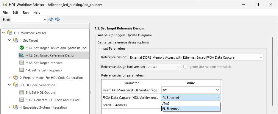
To run FPGA data capture over a PL Ethernet interface, in the 1.2. Set Target Reference Design step, set FPGA Data Capture (HDL Verifier required) to PL Ethernet.
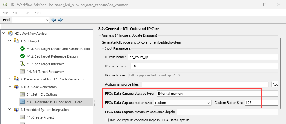
To expand the memory size for capturing the data, in the 3.2. Generate RTL Code and IP Core step, set FPGA Data Capture storage type to External memory and FPGA Data Capture buffer size to custom. Then, specify Custom Buffer Size as the required value, in powers of 2, represented as 2N, where N is an integer from 7 to 31.
By default, the External memory option for the PL Ethernet
interface is available for only the Kintex®-7 KC705 board (with the External DDR3 Memory Access with
Ethernet-Based FPGA Data Capture reference design). To enable this option
for other boards, configure the plugin_rd reference design definition
file by using the addFPGADataCaptureInterface method before you start the HDL Workflow
Advisor tool.
By default, the PL Ethernet connection is available for only the Artix®-7 35T Arty and Kintex-7 KC705 boards. To enable this connection for other AMD boards that have the Ethernet physical layer (PHY), manually add the Ethernet
media access controller (MAC) Hub IP in the plugin_board file by using
the addEthernetMACInterface method before you
start the HDL Workflow Advisor tool.
For an example, see Debug IP Core Using FPGA Data Capture. For more detailed generation and data capture steps, see Data Capture Workflow (HDL Verifier).
This feature requires an HDL Verifier license.
Generate IP cores for AMD ZCU208 and ZCU670 evaluation kits
HDL Coder now supports the AMD Zynq UltraScale+ RFSoC ZCU208 and DFE ZCU670 evaluation kits. For a full list of supported AMD devices, see Supported EDA Tools and Hardware.
You can generate the HDL code and IP cores for ZCU208 and ZCU670 boards. To see an example that shows how to generate an IP core for a Simulink model and to deploy it to the RFSoC boards, see DAC and ADC Data Loopback on RFSoC Device.
Reference designs for RFSoC boards
HDL Coder now supports the following reference designs for the AMD Zynq UltraScale+ RFSoC ZCU111, ZCU208, ZCU216, and DFE ZCU670 evaluation kits.
Default system— This is a basic reference design that supports data steaming between the processor and the FPGA. It also provides access to the PL-DDR4 memory.Real ADC/DAC Interface— This design receives and transmits real data and supports digital-to-analog converter (DAC) and analog-to-digital converter (ADC) real-time ports.IQ ADC/DAC Interface— This design receives and transmits complex in-phase/quadrature (I/Q) data and supports DAC and ADC real-time ports.
HDL Coder now supports the following reference designs for the AMD Zynq UltraScale+ RFSoC ZCU111, ZCU208, and ZCU216 evaluation kits.
Deep Learning design with real DAC/ADC interface— This design receives and transmits real data and supports DAC and ADC real-time ports. This deep learning reference design enables you to preprocess the received data, send the preprocessed data to the memory, and the deep learning processor processes the data.Deep Learning design with IQ DAC/ADC interface— This design receives and transmits complex I/Q data and supports DAC and ADC real-time ports. This deep learning reference design enables you to preprocess the received data, send the preprocessed data to the memory, and the deep learning processor processes the data.
Generate an IP core for a design under test (DUT) and integrate the generated IP core into these reference designs. Connect the IP core with rest of the design by using the AXI4-Stream master, AXI4-Stream slave, AXI4 Master, interrupt, AXI4-Lite, and DAC and ADC real or I/Q interfaces.
To target your algorithm in Simulink to the RFSoC reference design, specify it as the target reference design in the Configuration Parameters or HDL Workflow Advisor.
For more information about these reference designs, see Reference Designs for RFSoC Devices.
Functionality being removed or changed
Zynq RFSoC Template Builder tool has been removed
The Zynq RFSoC Template Builder tool has been removed. To target an RFSoC device, start with a new Simulink model or use the DAC and ADC Data Loopback on RFSoC Device example as a template.
Real ADC/DAC Interface with PL-DDR4 and IQ ADC/DAC
Interface with PL-DDR4 reference designs have been removed
The Real ADC/DAC Interface with PL-DDR4 and IQ ADC/DAC
Interface with PL-DDR4 reference designs have been removed. Instead,
use the Real ADC/DAC Interface and IQ ADC/DAC
Interface reference designs, respectively, for the same
capabilities.
For more information about the RFSoC reference designs, see Reference Designs for RFSoC Devices.
For models saved with removed reference designs, HDL Coder maps the old names to the updated names. You can generate HDL code and IP cores without making manual changes.
Real-Time Hardware Deployment
Automatically tune parameter values for dynamic switches
You can now automatically tune parameter values for dynamic switches in your optimized Simscape™ models for FPGA deployment. Tuned dynamic switches in the optimized model produce simulation results that match the simulation results of your Simscape model. This enhancement helps you compare the simulation results for your Simscape model and the optimized model.
To enable the parameter tuning for the dynamic switches in your optimized model, run
the sschdl.tuneOptimizedModel function at the MATLAB command prompt:
tunedParams = sschdl.tuneOptimizedModel(originalModel,optimizedModel=optModel);
Here, the input originalModel is your original Simscape model containing ideal Simscape switches, and optMdl is
your optimized model containing dynamic switches. The output
tunedParams is a structure containing the tuned parameter values
for the dynamic switches. If you have a license for Simulink
Design Optimization™ toolbox, you can enable fine-tuning of the parameter values by setting the
name-value argument FineTune to true.
tunedParams = sschdl.tuneOptimizedModel(originalModel,optimizedModel=optModel,...
FineTune=true);
The sschdl.generateOptimizedModel function generates an optimized model by
replacing the Simscape switches and converter blocks with their dynamic equivalents.
This function automatically tunes the parameter values for dynamic switches to
Conductance, Gs or
Ion/Voff,
where Ion is the closed circuit current and
Voff is the open circuit voltage of the
switch.
You can fine-tune the parameters while generating the optimized model.
To enable fine-tuning with sschdl.generateOptimizedModel
function, run this command at the MATLAB
command
prompt:
generatedModel = sschdl.generateOptimizedModel(originalModel,FineTune=true);
Previously, you had to tune the dynamic switch parameter values manually, and automatic parameter tuning was not supported when generating an optimized model from your Simscape plant model.
For more information on parameter tuning, see Tune Parameter Values for Dynamic Switches in Synchronous Buck Converter and Generate HDL Code for Simscape Models by Using Dynamic Switch Approximation.
Simscape HDL Workflow Advisor: Optimized data extraction for Linear Time-Invariant models
Starting in R2026a, the Simscape HDL Workflow Advisor optimizes the simulation of linear time-invariant (LTI) models during the State-space conversion step by caching the state-space matrices in a single simulation time step.
In the State-space conversion step, the Advisor extracts state-space data from the Simscape model. The generated HDL implementation model uses this cached data to calculate the updated state at each simulation time step. For switched linear Simscape models, the simulation must run until the simulation stop time to capture all the state-space data. For LTI models, the Advisor now captures all required state-space data in a single simulation step, eliminating the need to run the simulation until stop time and reducing the simulation run time.
Fixed-point data type support for optimized PMSM block
Fixed-point data type precision is now supported for the optimized PMSM block when you generate an optimized model by replacing a Simscape PMSM (Simscape Electrical) block with an equivalent optimized PMSM block. With this enhancement, you can achieve better timing and resource utilization for Simscape models containing Simscape PMSM blocks.
Consider the sschdlexPMSMDriveOptimizedMotor model from the Optimize Simscape Three-Phase PMSM Drive example on a Windows® 11
Intel®
Xeon® W-2133 CPU @3.60GHz test system with target device family set to
AMD
Kintex 7 and device part set to xc7k325t. The table shows the
improvements in the FPGA sampling frequency for Single and
Fixed-point data type precision on running synthesis for
the generated HDL code:
| Example Model | Data Type Precision | FPGA Sampling Frequency |
|---|---|---|
sschdlexPMSMDriveOptimizedMotor | Single | ~1.5 MHz |
sschdlexPMSMDriveOptimizedMotor | Fixed-point | ~6 MHz |
For an example on how to use fixed-point data type precision for an optimized PMSM block, see Generate Optimized Simscape Three-Phase PMSM Drive Model for Real-Time FPGA HIL Deployment.
Before R2026a, only single and double data type precisions were supported for an optimized PMSM block.
Avoid CPU overloads during real-time simulation by handling CPU and FPGA rate transitions
Sometimes a real-time application running on the target computer does not have enough time to complete processing before the next time step. This condition is called CPU overload.
To avoid CPU overload during execution, you must ensure that all the sample rates in the generated Simulink Real-Time (SLRT) interface model are within the range that the CPUs can process. For hardware deployment, exclude any FPGA-related faster sample rates from the SLRT interface model. To achieve this in the Simscape model:
Insert Rate Transition blocks at the input and output ports of the Simscape subsystem that you want to map to the PCIe interface.
Set the Output port sample time block parameter to -1.
Add a Signal Specification block in the Simscape subsystem and set the Sample time block parameter to the FPGA rate.
These settings can reduce CPU overloads encountered during hardware deployment of your plant model. For more information, see Modeling Best Practices for FPGA HIL Deployment.
HDL code generation for PWM Generator (Three-phase, Two-level) block
The Simscape Hardware-in-the-Loop (HIL) workflow now supports HDL code generation for the PWM Generator (Three-phase, Two-level) (Simscape Electrical) block. This enhancement enables you to deploy the PWM Generator (Three-phase, Two-level) block onto the FPGA board.
Previously, you could not deploy PWM Generator (Three-phase, Two-level) blocks in your plant model on the target hardware.
Simscape Hardware-in-the-Loop workflow: Reference applications
The new Real-Time Simulation of Dual Active Bridge Converter on FPGA example shows how to model a dual active bridge (DAB) converter with two full-bridges and control the output voltage of the circuit. The converter is modeled using the dynamic switch approximation method. For the DAB converter model, you can generate HDL code, synthesize the code, and deploy onto target hardware.
Functionality being removed or changed
Using model name as input argument of sschdladvisor function not
recommended
Still runs
Starting in R2026a, using the model name as the input argument of sschdladvisor function is not recommended.
sschdladvisor("modelName")To get optimized results on hardware, use a subsystem name as the input argument instead.
sschdladvisor("subsystemName")This syntax runs the Simscape HDL Workflow Advisor for the subsystem containing the parts of the Simscape model that you want to deploy onto the hardware.