Debug Write Registers Using Readback in Generated IP Cores
This example describes the different techniques to read the input registers such as AXI4 or AXI4-Lite in your design. It shows the process of how to enable readback on input registers and read the values of input registers for your design.
Introduction
You can select the AXI4 or AXI4-Lite interface in the IP core generation or the Simulink® Real-Time™ FPGA I/O workflow in HDL Workflow Advisor. By default, your IP is generated without the readback capability of the AXI4 or AXI4-Lite input registers. When the readback feature is enabled from HDL Workflow Advisor or from command-line interface, you can read the values of input registers. This technique is useful for debugging the input values, which are written into AXI4 or AXI4-Lite interface. The figure shows the AXI4 subordinate interface and its registers.

Enabling Write Register Readback
1. When your design contains the AXI4 or AXI4 Lite interface, you can perform the readback of AXI4 registers. You can use any model which has these interfaces. Use hdlcoder_led_blinking or hdlcoder_led_blinking_4bit model. Open the Simulink model that implements LED blinking by entering this command:
open_system('hdlcoder_led_blinking');
2. Run all the tasks up until Set HDL Options.
3. You can turn on the readback on input registers by using the HDL workflow Advisor or by using the command-line interface. Generate RTL code and IP Core, by default, the readback on input register is turned off. To enable this option, select Enable readback on write registers under the Generate RTL Code and IP Core task of HDL Workflow Advisor.

You can also enable the readback option at the MATLAB® command line by using the hdlset_param function.
hdlset_param('hdlcoder_led_blinking/led_counter','WriteRegisterReadback','on');
hdlset_param('hdlcoder_led_blinking/led_counter','RegisterInterfaceReadPipeline',2);
Read Values of the AXI4 input registers
After setting the readback option for your model, generate the RTL code and the IP Core in the HDL Workflow Advisor or through the command-line interface (CLI). Once the IP core is generated, the IP Core Generation Report is generated in the code generation report. The IP Core Generation Report contains the details about the Target Platform Interface of your model. The figure shows the AXI-Lite interface mapped to the hdlcoder_led_blinking model ports. The table in the IP Core Generation Report shows the interface mapping address of each register. These addresses are used to read the input registers.

The Register base address is used together with interface mapping address to read the value of input registers. These address mapping details are used to read the AXI4 registers. You can perform the readback of input registers in these ways:
Using the MATLAB FPGA Prototyping API Script
Using the JTAG AXI Manager
Using the Devmem command
To read the value, you can use any of the preceding techniques. Then you must complete all the steps in HDL Workflow Advisor. Once the bitstream is generated and programmed into the target device, perform readback of input registers.
Readback of Input Registers by Using MATLAB FPGA Prototyping API Script
You can read input registers by using MATLAB® FPGA prototyping API scripts. Once the RTL code and IP core are generated, host interface scripts can be generated by using the Generate Software Interface task from the HDL Workflow Advisor. The option Generate host interface script generates the MATLAB prototyping API scripts.
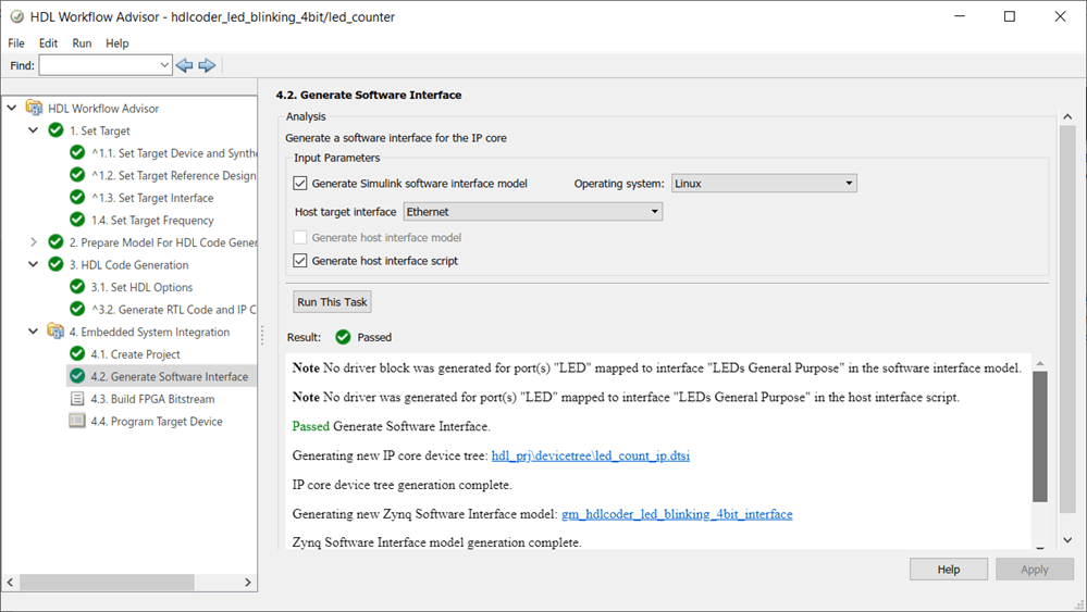
This option generates two scripts that are interface and setup scripts, shown here for the hdlcoder_led_blinking model.
![]()
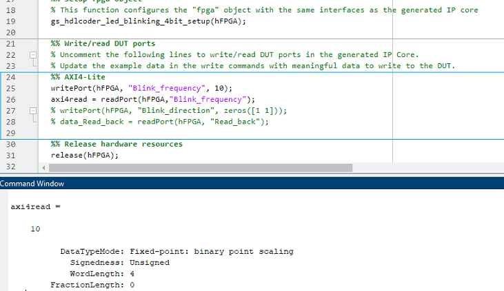
The setup function contains commands for the register interfaces(AXI4/AXI4-Lite) that HDL Coder uses to control the DUT ports in the generated HDL IP core, which are mapped to their corresponding interfaces.

The host interface script instantiates this setup function to connect to the target and send read or write commands. You can uncomment and send meaningful data by using the inputs to the DUT in your original model. After interfacing with the hardware, the script disconnects from the hardware resource associated with the FPGA object.

Generate the bitstream and program the target device. To write and read the data for blink_frequency, modify the interface script and run the script. The value 10 is written to the blink_frequency and axi4read shows the readback of blink_frequency.
MATLAB prototyping API uses JTAG AXI Manager for readback of input registers. For more information, see Generate and Manage FPGA I/O Host Interface Scripts.
Readback of Input Registers by Using JTAG AXI Manager
You can also use separately the JTAG AXI Manager for readback of input registers. To use JTAG AXI Manager, you must insert the JTAG AXI Manager IP into reference design.

Set the necessary options for enabling readback as mentioned in earlier section and follow the example Debug and Control Generated HDL IP Core by Using JTAG AXI Manager for more details.
Readback of Input Registers by Using Devmem Command (Probe Registers from Target)
You can use the devmem command in Putty or a hyper terminal. Once you program the bitstream into the target device, open Putty or hyper terminal by using the serial interface. To use devmem command for the hdlcoder_led_blinking model:
1. Read the data from address '400D0100':
devmem 0x400D0100
You get the value as 0x00000000.
2. Write some value in address '400D0100':
devmem 0x400D0100 w 0x1
3. Reread the address '400D0100':
devmem 0x400D0100
You get the value as 0x00000001.

In this way scalars can be read. In the vector data type, you first need to write the data on the register, and then write 0x1 to the strobe address as in vector mode strobe synchronization done for writing. After writing on strobe address, the customer reads the data on the register by using same address. The figure shows the writing and reading of the values in the vector data type by using devmem.
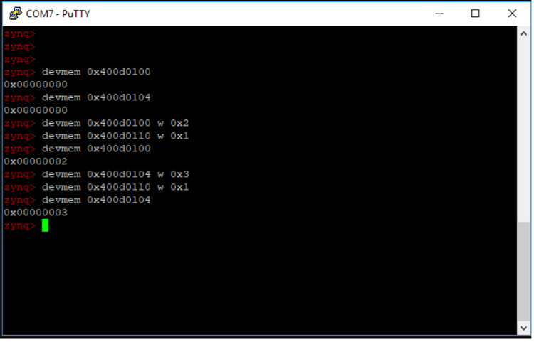
1. Try to read the address 0x400D0100 and 0x400D0104, which shows as 0.
2. Try writing 0x2 on address 0x400D0100, and then write 0x1 on strobe address 0x400D0110.
3. Read the data on address 0x400D0100. It shows as 0x00000002.
4. Write 0x3 on address 0x400D0104, and then write 0x1 on strobe address 0x400D0110.
5. Read the data on address 0x400D0104. It shows 0x00000003.
Register Interface Read Pipeline
When your model contains several output registers and you want to read back data from multiple registers, the read back logic can impact the synthesis frequency. Starting in R2024b, HDL Coder™ optimizes this by using a single multiplexer in the address decoder, implemented as a case statement in the generated HDL code. This modified mux architecture replaces the long mux chain architecture used before R2024b. After you build the bitstream, if the timing closure is not met and the critical path is in the read address decoder, you can optimize the timing by adjusting the Register interface read pipeline parameter. For more information, see Optimize Timing on Register Interface.
Enabling Input Register Readback for Individual Ports
If your design contains a large number of input ports and you enable readback on all of the input ports, your design can consume lot of resources and can have timing violations.
Instead of enabling the global readback on all the input ports, You can enable the readback for individual ports based on your requirement.
1. Below is the example Simulink model which contains large number of input ports.
open_system('hdlcoder_portlevel_readback');
2. Run all the tasks up until Set Target Interface under Set Target of the HDL Workflow Advisor.
You can turn on the readback for any of the individual ports by clicking the Options under Interface Options.
In the Set Interface Options window, you can set the Enable write register readback option to on, off or inherit. By default, the Enable write register readback option is set to inherit, where the readback on that port will inherit from the global readback option.

You can also turn on the readback for any individual port at the MATLAB command line by using hdlset_param function in the exported script.
hdlset_param('hdlcoder_portlevel_readback/DUT/In1','IOInterfaceOptions',{'RegisterInitialValue','0','EnableReadback','on'});
Utilization Summary for Port Level Readback and Global Readback
This table shows the resource utilization for different cases of port level readback and global readback for the hdlcoder_portlevel_readback model. The Register interface read pipeline parameter is adjusted in each case to meet timing requirements. The target frequency for all the cases is 250 MHz.
Resource | Available | Case 1 Global = OFF Port level = Inherit Read pipeline = 0 | Case 2 Global = OFF Port level = ON (20 ports) Read pipeline = 2 | Case 3 Global = ON Port level = Inherit Read pipeline = 2 |
LUT | 218600 | 2797 | 3010 | 3639 |
LUTRAM | 70400 | 191 | 191 | 191 |
FF | 437200 | 9820 | 10678 | 10988 |
Number of total readable registers | 149 | 206 | 297 |
Case 1*: The global and port level readbacks are set to off for all the ports. Register interface read pipeline is set to 0**.***
Case 2*: The port level readback is enabled for the first 20 input ports. Register interface read pipeline is set to 2**.***
Case 3*: The global readback is enabled for all the input ports. Register interface read pipeline is set to 2**.***
For cases two and three, the number of readable registers is greater than 200. When you generate a bitstream with the default value of the Register interface read pipeline parameter set to zero, the timing closure is not met for the operating frequency of 250 MHz as shown in this image:

When you open the Vivado project to access the timing analysis and check the critical path, the critical path is in the address decoder. Use the Register interface read pipeline parameter to achieve the desired frequency. This image shows the start and end points of the critical path:

When you set the Register interface read pipeline parameter to 2 you can build the bitstream without timing errors.

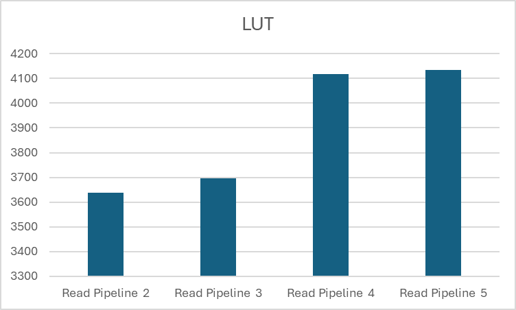
When you must run the DUT at higher clock frequencies, you can increase the Register interface read pipeline parameter value. When you increase the parameter value the design meets the timing, however latency is added to the read channel and resource usage increases. This graph shows the resource usage for different values of the Register interface read pipeline parameter for case three (readback enabled for all input ports):