Get Started with IP Core Generation from MATLAB Function
R2026bThis example shows how to use the MATLAB® HDL Workflow Advisor to generate a customized IP core that blinks LEDs on an FPGA board. This example deploys the generated IP core on the ZedBoard hardware, but you can use any Xilinx® Zynq® platform or Xilinx FPGA with a MicroBlaze processor.
Introduction
You can use MATLAB to design, simulate, and verify your application, perform what-if scenarios with algorithms, and optimize parameters. You can then prepare your application design for hardware and software implementation on your FPGA board and decide which elements are performed by the programmable logic and which elements run on the processor.
In this example, you can:
Set up your Zynq hardware and tools.
Review your design for hardware and software implementation.
Convert your MATLAB algorithm to HDL code using HDL Coder.
Generate an HDL IP core by using the MATLAB HDL Workflow Advisor.
Deploy the IP core to Zynq hardware.
Additionally, you can use this IP core in other designs or projects to enhance and build upon its functionality.
Prerequisites
Install Xilinx Vivado®. For a list of supported versions, see HDL Language Support and Supported Third-Party Tools and Hardware.
Set the path to the installed synthesis tool for the target device by using the
hdlsetuptoolpathfunction. In the MATLAB Command Window, use this command, making sure to replace the path with your installation path.
hdlsetuptoolpath('ToolName','Xilinx Vivado','ToolPath',vivadopath);
Set up the ZedBoard. Refer to the "Set up Zynq Hardware and Tools" section in Get Started with IP Core Generation from Simulink Model for more information.
In this example, you implement the
mlhdlc_ip_core_led_blinkingfunction on the ZedBoard. Open and save a local copy of the function:
open mlhdlc_ip_core_led_blinking.mOpen and save a local copy of the MATLAB test bench.
open mlhdlc_ip_core_led_blinking_tb.mReview and Partition Design for Hardware and Software Implementation
To generate and deploy an IP core from a MATLAB algorithm, you need three components:
A MATLAB function that runs on the hardware.
A MATLAB test bench that exercises the function design in MATLAB.
MATLAB scripts that prototype the deployed MATLAB function on the hardware. Prototyping using MATLAB is optional, but provides an additional means of IP core verification.
To effectively implement your design, you must:
Distinguish between the parts of the algorithm that are suitable for programmable logic and the parts that are suitable for the ARM® processor.
Group the algorithm parts for the programmable logic into a MATLAB function.
Use the MATLAB function as the boundary for your hardware-software partition.
Use HDL Coder to implement the MATLAB code in this function on programmable logic.
Open the mlhdlc_ip_core_led_blinking function to examine how it is partitioned.
open mlhdlc_ip_core_led_blinking.mThis function models a counter that blinks LEDs on an FPGA board. It has two inputs, Blink_frequency and Blink_direction, which determine the LED blink frequency and direction. The output, LED, connects to the LED hardware found on the board and the output, Read_back is set to the count value and can be read back to the processor.
Open the mlhdlc_ip_core_led_blinking_tb test bench to examine how it exercises the function design.
open mlhdlc_ip_core_led_blinking_tb.mThe test bench provides a range of input conditions to the mlhdlc_ip_core_led_blinking function.
Create MATLAB HDL Coder Project
Create an HDL Coder project by entering this command in the MATLAB Command Window.
coder -hdlcoder -new blinkingLEDmatlab
Alternatively, to create a MATLAB HDL Coder project:
In the MATLAB Editor, in the Apps tab, select HDL Coder. In the Create HDL Coder Project dialog box, set Name to
blinkingLEDmatlab.mldatx. Set Folder to the current working directory. Click OK to create theblinkingLEDmatlab.mldatxproject in the specified directory and open the HDL Workflow Advisor.In the HDL Workflow Advisor, in the Define Input Types task, for the MATLAB Function parameter, click Browse to browse to the MATLAB function file
mlhdlc_ip_core_led_blinking.m. Click Open to add the MATLAB function file to the project. For the MATLAB Test Bench parameter, click the button to browse to the MATLAB test bench file
 mlhdlc_ip_core_led_blinking_tb.m. Click Open to add the MATLAB test bench file to the project. You must add a MATLAB test bench unless the design does not need fixed-point conversion and you do not want to generate a register transfer level test bench.Click the Run button. The HDL Workflow Advisor infers the input types automatically by executing the MATLAB test bench. If you do not add a test bench, you must define the inputs to the top-level MATLAB function.
Using the Workflow Advisor, perform a fixed-point conversion:
Click on the Fixed-Point Conversion step. Click Analyze Design. The design is compiled with the input types defined in the previous step and after the compilation is successful the variable table shows inferred types for all the functions in the design. In this step, the original design is instrumented so that the minimum and maximum values for all variables in the design are collected during simulation.
Click the Propose Types button. Fixed-point types are proposed based on the default word length settings.
Click the Validate Types button. Note that the proposed type for
blinkFrequencyOutis set tonumerictype(0,24,0).
For an overview on fixed-point conversion, see Floating-Point to Fixed-Point Conversion. For a more comprehensive tutorial on creating and populating MATLAB HDL Coder projects, see Generate HDL Code from MATLAB Algorithms.
Define Code Generation Target
You can generate a shareable and reusable IP core using the MATLAB HDL Workflow Advisor. HDL Coder integration with the Xilinx Vivado IDE facilitates the incorporation of the generated IP core into the FPGA design.
For an overview of how to generate an IP core for a specific hardware platform, see Targeting FPGA and SoC Hardware Overview.
Perform IP Core Generation using the MATLAB HDL Workflow Advisor:
In the MATLAB HDL Workflow Advisor, click Select Code Generation Target.
Set Workflow to
IP Core Generation.
Specify Platform
In order to integrate the generated IP core in a reference design, set Platform to a target platform:
Generic Xilinx Platform: This is a board-independent option that generates a generic Xilinx IP core. However, you must manually integrate the IP core into an existing Xilinx Vivado project.
Board-specific platforms: These options are specific to Xilinx boards and integrate the IP core into a predefined reference design. This integration uses the Xilinx Vivado with IP Integrator embedded system tool.
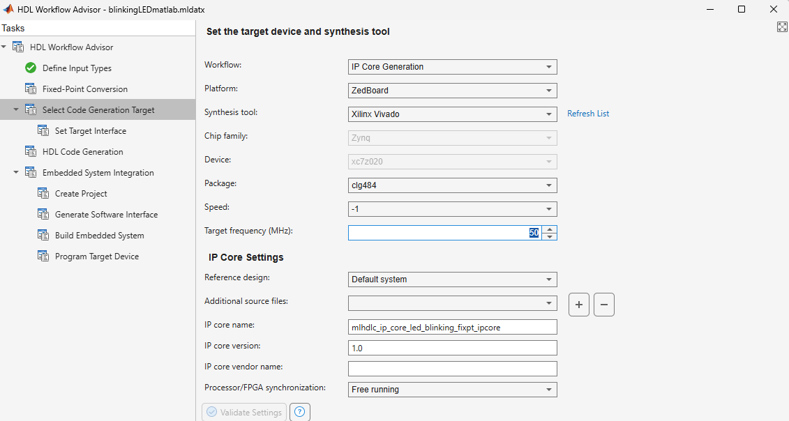
In this example, you target a ZedBoard platform. Set these parameters:
Set Platform to
ZedBoard.Set Synthesis tool to
Xilinx Vivado.Set Target Frequency (MHz) to
50.Under IP core settings, set Reference design to
Default system.
Configure Target Interfaces
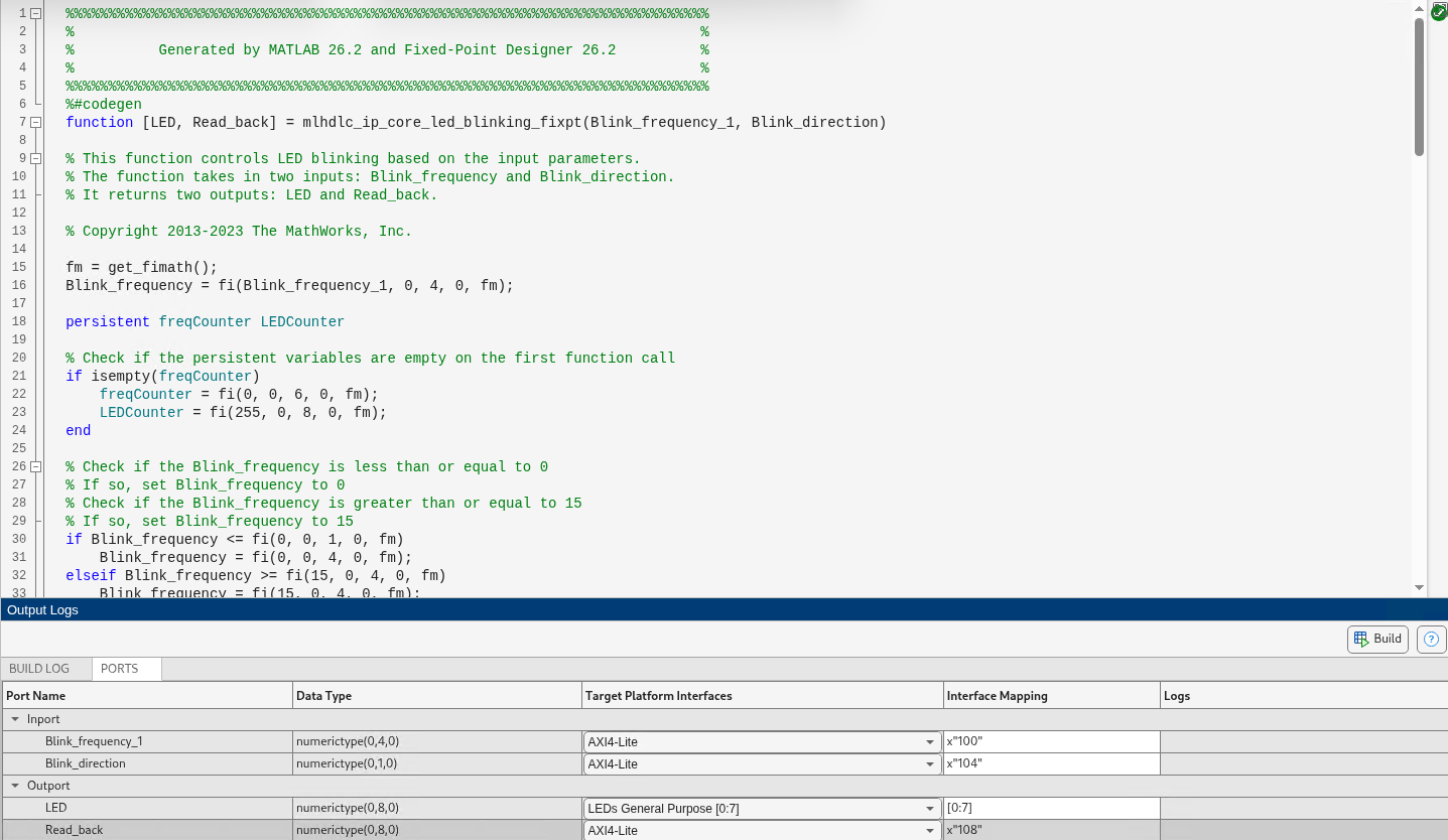
Next, you use the Set Target Interface sub task to map each input and output in the MATLAB design function to one of the IP core target interfaces.
In this example, map inputs Blink_frequency and Blink_direction, along with the output Read_back to the AXI4-Lite interface. HDL Coder generates AXI accessible registers for them. Map the LED output to an external interface, LEDs General Purpose [0:7], which connects to the LED hardware on the ZedBoard.
In the bottom pane, in the Ports tab, in the Target Platform Interfaces column, set the target platform interface for the
Blink_frequency,Blink_direction, andRead_backvariables to theAXI4-Liteinterface.In the bottom pane, in the Ports tab, in the Target Platform Interfaces column, set the target platform interface for the
LEDvariable to theLEDs General Purpose [0:7]external interface.Right-click the Set Target Interface sub task and select Run to Selected Task.
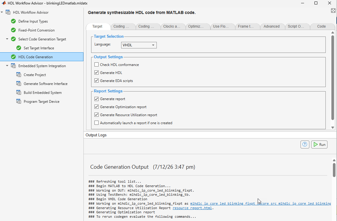
To generate the IP core and IP core report, right-click the HDL Code Generation task and select Run this task.
Integrate Generated IP Core with Xilinx Vivado Environment
After generating the IP core, you integrate it with a reference design, then synthesize and download the bitstream to the FPGA within the MATLAB HDL Workflow Advisor.
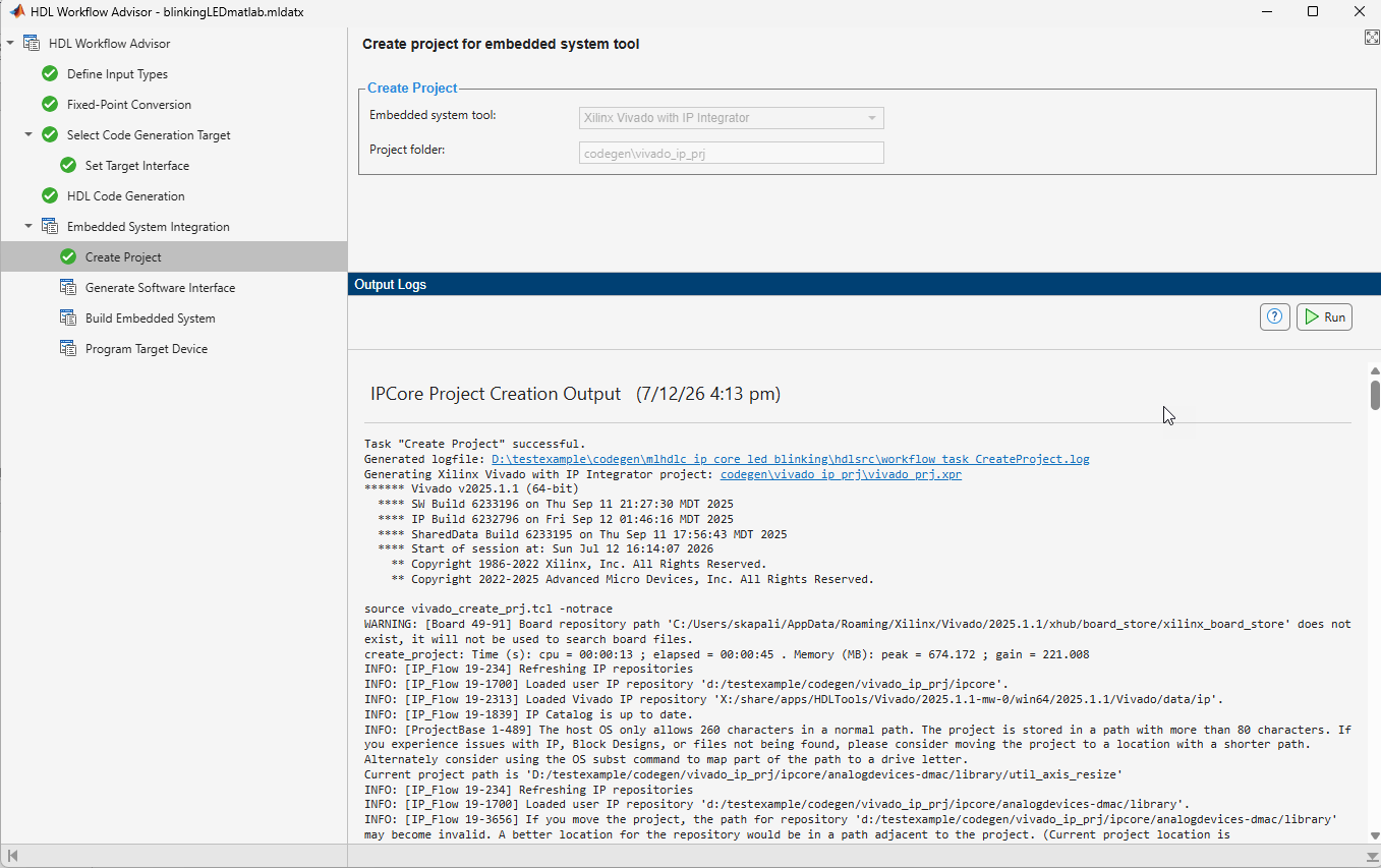
1. Under the Embedded System Integration task, right-click the Create Project sub task and select Run This Task. A Xilinx Vivado project is generated that integrates the IP core in a predefined reference design by leveraging the IP Integrator embedded system tool. The dialog box includes a link to open the project in Vivado.
2. Right click the Generate Software Interface sub task, and select Run This Task. This sub task generates interface gs_mlhdlc_ip_core_led_blinking_fixpt_interface.m and setup gs_mlhdlc_ip_core_led_blinking_fixpt_setup.m scripts in the current folder. These scripts set up and interface with the generated and deployed IP core by writing to the AXI accessible registers. Click on the generated hyperlink to open the script.
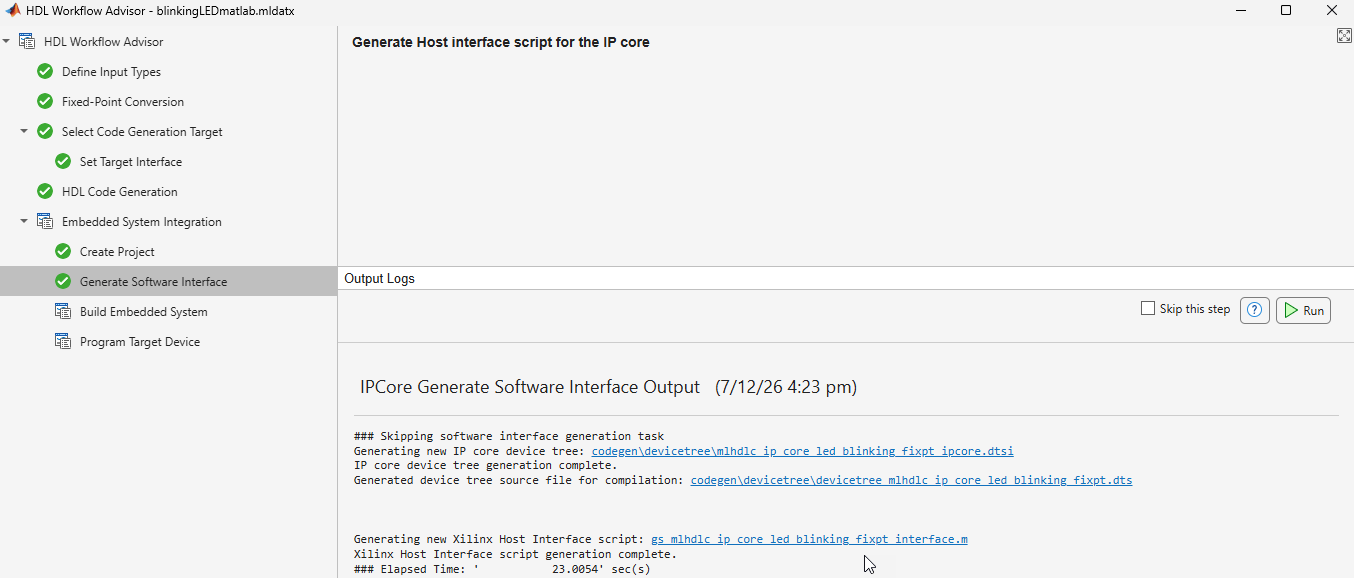
Note: The interface and setup files are generated only if the selected Platform has Processing system. You can skip the sub task if the Platform does not have processing system.
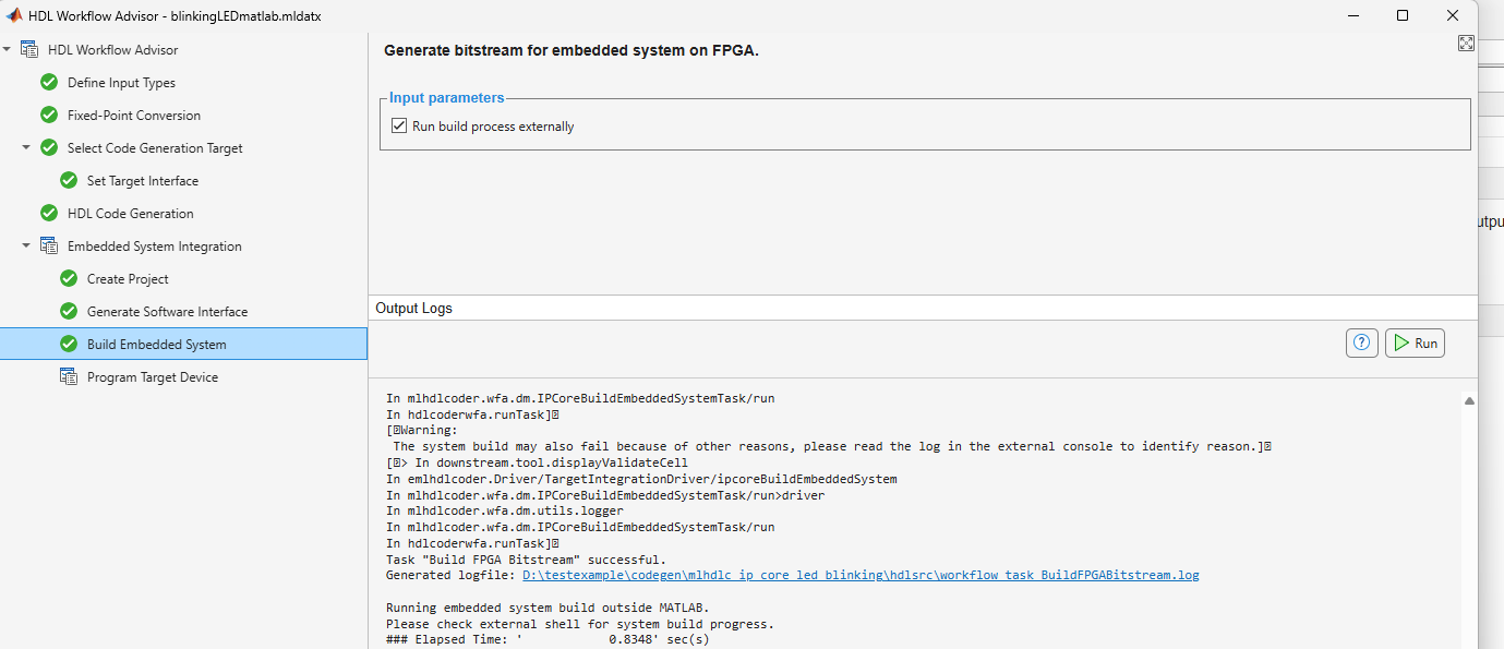
3. In the Build Embedded System sub task, select Run build process externally, then click Run. The Xilinx synthesis tool runs as a separate process outside of MATLAB. Wait for the synthesis tool to complete.
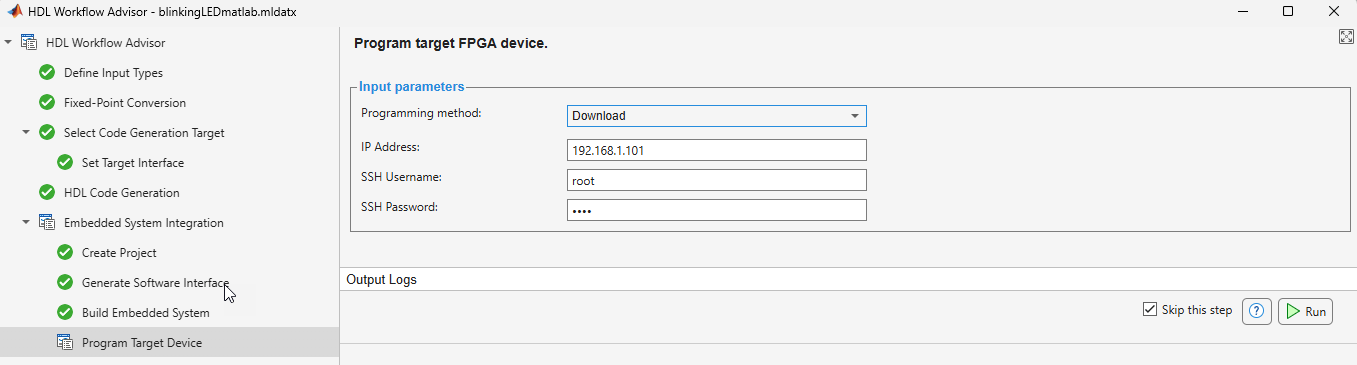
4. After generating the bitstream, right-click the Program Target Device sub task and
Set Programming method to
DownloadSet IP Address to you target board IP address. For example,
192.168.1.101Set SSH Username and SSH Password to your target board username and password. For example, the default username and password is
root.
Click Run to program the ZedBoard. The LEDs start blinking on the ZedBoard after programming the FPGA hardware.
Prototype and Verify IP Core on Hardware
To verify the generated IP core on the ZedBoard hardware, use the generated MATLAB files from the Generate Software Interface sub task, gs_mlhdlc_ip_core_led_blinking_fixpt_interface.m and gs_mlhdlc_ip_core_led_blinking_fixpt_setup.m. These files contain MATLAB commands that connect your hardware and interact with your IP core.
Open the generated interface gs_mlhdlc_ip_core_led_blinking_fixpt_interface.m and setup gs_mlhdlc_ip_core_led_blinking_fixpt_setup.m files. The files are generated in the same folder as the IP core.
The gs_mlhdlc_ip_core_led_blinking_fixpt_interface script establishes a connection to your FPGA hardware and uses the gs_mlhdlc_ip_core_led_blinking_fixpt_setup function to enable data reading and writing by configuring the fpga hardware object with the mapped ports and interfaces from the Set Target Interface sub task.
You can reuse this function in your own scripts to replicate the same configuration. For example, in the gs_mlhdlc_ip_core_led_blinking_fixpt_interface.m script uncomment and modify this line to change the LED blink frequency.
% writePort(testFPGA, "Blink_frequency_1", 0);
Run the modified script and observe the LED blink frequency changing on the hardware. Additionally, in the gs_mlhdlc_ip_core_led_blinking_fixpt_interface.m script uncomment this line and run the script to observe the changes in the data_Read_back variable in the MATLAB workspace.
% data_Read_back = readPort(testFPGA, "Read_back");
For more information regarding Host Interface Scripts, see Generate and Manage FPGA I/O Host Interface Scripts

