BLDC HDL
Libraries:
Motor Control Blockset HDL Support /
Electrical Systems /
Motors
Description
The BLDC block implements a three-phase brushless DC (BLDC) motor with a trapezoidal back electromotive force that remains constant for a position range of 120 electrical degrees. The block uses the three-phase input voltages to regulate the individual phase currents, allowing control of the motor torque or speed.
Motor Construction
This figure shows a motor with a single pole pair.
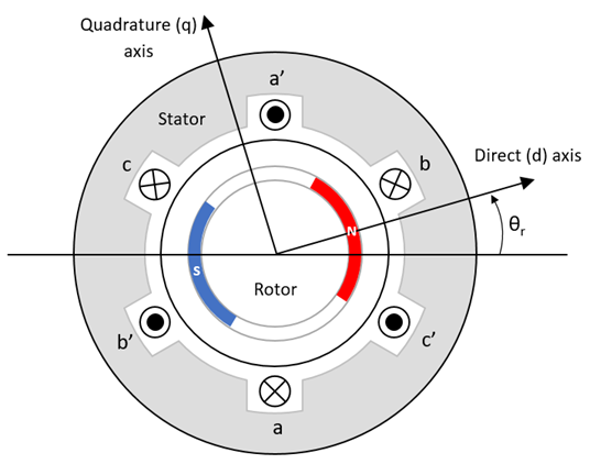
The rotor magnetic field due to the permanent magnets creates a trapezoidal rate of change of flux with the motor angle.
For the axes convention, the phase-a aligns with d-axis when the motor angle θr is zero.
Three-Phase Sinusoidal Model Electrical System
Instead of the standard dq reference frame, the block uses d’q’ reference frame, which is defined by these transformation equations.
The block implements these equations expressed in the dq and d’q’ reference frame of the BLDC motor. All quantities in the motor reference frame are with respect to the stator phase A.
This table describes the variables used in these equations.
|
Lq , Ld |
q- and d-axis inductances (H) |
|
R |
Resistance of the stator windings (ohm) |
|
iq' , id' |
q'- and d'-axis currents (A) |
|
vq' , vd' |
q'- and d'-axis voltages (V) |
|
ωm |
Angular mechanical velocity of the motor (rad/s) |
|
ωe |
Angular electrical velocity of the motor (rad/s) |
|
P |
Number of pole pairs |
|
Te |
Electromagnetic torque (Nm) |
θe |
Electrical angle (rad) |
va , vb , vc |
Stator phase A, B, and C voltages (V) |
|
ia , ib , ic |
Stator phase A, B, and C currents (A) |
|
Ea , Eb , Ec | Back EMF of stator phases A, B, and C (Vpk_LL/krpm (peak voltage (line-to-line) per kilo revolution per minute)) |
ψa , ψb , ψc |
Total fluxes linking each stator winding (Wb) |
Mechanical System
The motor angular velocity is given by:
The equations use these variables.
J | Combined inertia of motor and load (kgm^2) |
F | Combined viscous friction of motor and load (N·m/(rad/s)) |
θm | Motor mechanical angular position (rad) |
Tm | Motor shaft torque (Nm) |
Te | Electromagnetic torque (Nm) |
Tf | Motor shaft static friction torque (Nm) |
ωm | Angular mechanical velocity of the motor (rad/s) |
Amplitude Invariant dq Transformation
The block uses these equations to implement amplitude invariant dq transformation to ensure that the dq and three phase amplitudes are equal.
The equations use these variables.
Θda | dq stator electrical angle with respect to the rotor a-axis (rad) |
vsq, vsd | Stator q- and d-axis voltages (V) |
isq, isd | Stator q- and d-axis currents (A) |
| va, vb, vc | Stator voltage phases a, b, c (V) |
| ia, ib, ic | Stator currents phases a, b, c (A) |
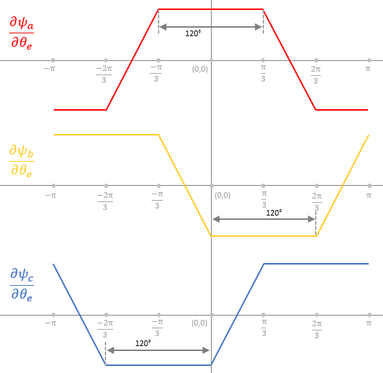
Trapezoidal Rate of Change of Flux
The rotor magnetic field due to the permanent magnets create a trapezoidal rate of change of flux with the rotor angle. This figure shows the rate of change of flux for the three phases of a three-phase BLDC motor.
Examples
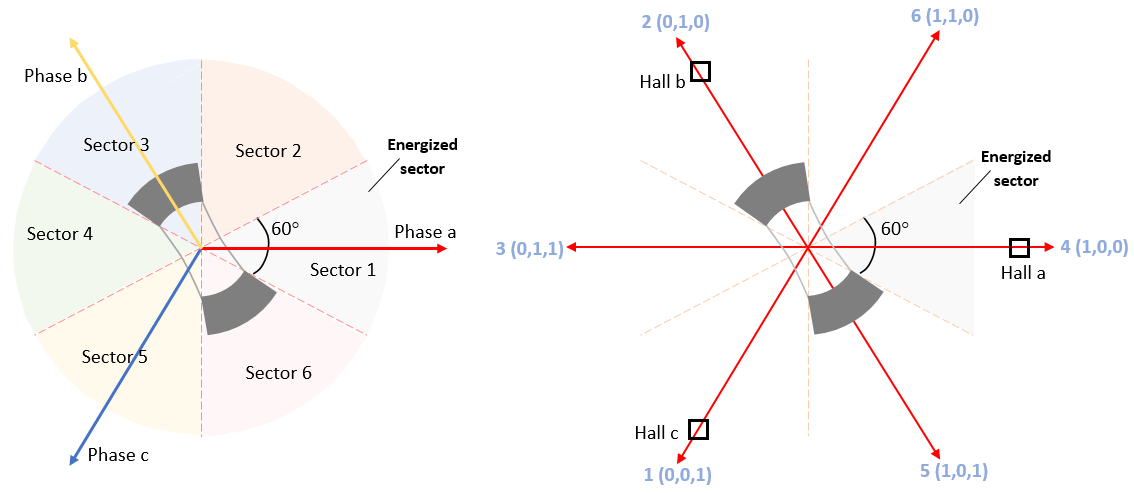
Six-Step Commutation of BLDC Motor Using Sensor Feedback
Use six-step commutation technique to control speed and direction of rotation of a three-phase BLDC motor.
Ports
Input
Output
Parameters
Extended Capabilities
Version History
Introduced in R2023b