Introduction to Reconfigurable Intelligent Surfaces (RIS)
With the deployment of 5G wireless systems, industry has started to explore systems beyond 5G, such as 6G wireless networks. After all, the quest for higher data rate is never ending. In the last several years, reconfigurable intelligent surface (RIS) has emerged to be a key enabling technology for 6G systems. This example shows how you can model such a system with Phased Array System Toolbox™. The focus of this example is to model the RIS with a deterministic channel model. For a stochastic RIS channel model, see the Model Reconfigurable Intelligent Surfaces with CDL Channels (5G Toolbox) example.
Introduction
Since the appearance of 4G systems, antenna arrays have become a critical part in both the base stations and the user equipment (UE). The mmWave bands adopted for 5G systems make it possible to pack larger arrays (in terms of number of elements) into a tight space. In return, the beamforming gain provided by these arrays help to compensate the severe propagation loss in these mmWave bands so the desired data rate and capacity can be achieved.
On the other hand, moving to mmWave bands also means that wireless systems beyond 5G will increasingly rely on a line of sight (LOS) link, in contrast to a scatterer rich environment in sub 6GHz bands. Therefore, if an LOS link cannot be established, the performance of the system suffers. This prompts engineers to seek if there is a way to improve the propagation environment. During this pursuit, the reconfigurable intelligent surface (RIS) technique has emerged as a suitable candidate for such a purpose.
An RIS, sometimes also called an intelligent reflecting surface (IRS), is a passive planar array formed by many elements. It is important to highlight that the surface is passive, thus keeping the cost low as there is no need to include radio frequency (RF) circuits in the surface. However, each element can adjust phases of the reflected signal so a controller could coherently combine them by adjusting phase at each element. Currently, there are two approaches to form such a surface [1]. The first approach is to use a reflectarray with a phase shifter for each element. This works a lot like traditional passive phased arrays. An alternative approach is to build the surface with a metasurface. By modifying the meta material characteristics, the reflected signal from a given element can be modified. Compared to a reflectarray, the elements in a metasurface can be much closer to each other, which makes the entire aperture more compact.
Next section creates a 10-by-20 RIS with omnidirectional elements with half wavelength spacing. The carrier frequency is set to 28 GHz. It is possible to use a custom element pattern if desired. For more information regarding how to perform an electromagnetic analysis of an RIS surface, refer to the Electromagnetic Analysis of Reconfigurable Intelligent Surface (Antenna Toolbox) example.
fc = 28e9;
c = physconst('lightspeed');
lambda = c/fc;
rng(2023);

% Setup surface
Nr = 10;
Nc = 20;
dr = 0.5*lambda;
dc = 0.5*lambda;

% construct surface
ris = phased.RectangularRIS('Size',[Nr Nc],'Spacing',[dr dc],'UnitCell',phased.IsotropicAntennaElement)
ris =
  phased.RectangularRIS with properties:

    UnitCell: [1×1 phased.IsotropicAntennaElement]
        Size: [10 20]
     Spacing: [0.0054 0.0054]
Simulation Scenario
To illustrate the benefit of using an RIS, we will set up a scene as depicted below [2]. Without losing any generality, assume the base station, the RIS, and the UE are all static and in the xy plane. The base station is at the origin; the RIS is at dbr meters away along x axis; and the UE is at du meters away along x axis and 5 meters away along y axis. Set both dbr and du to 50.
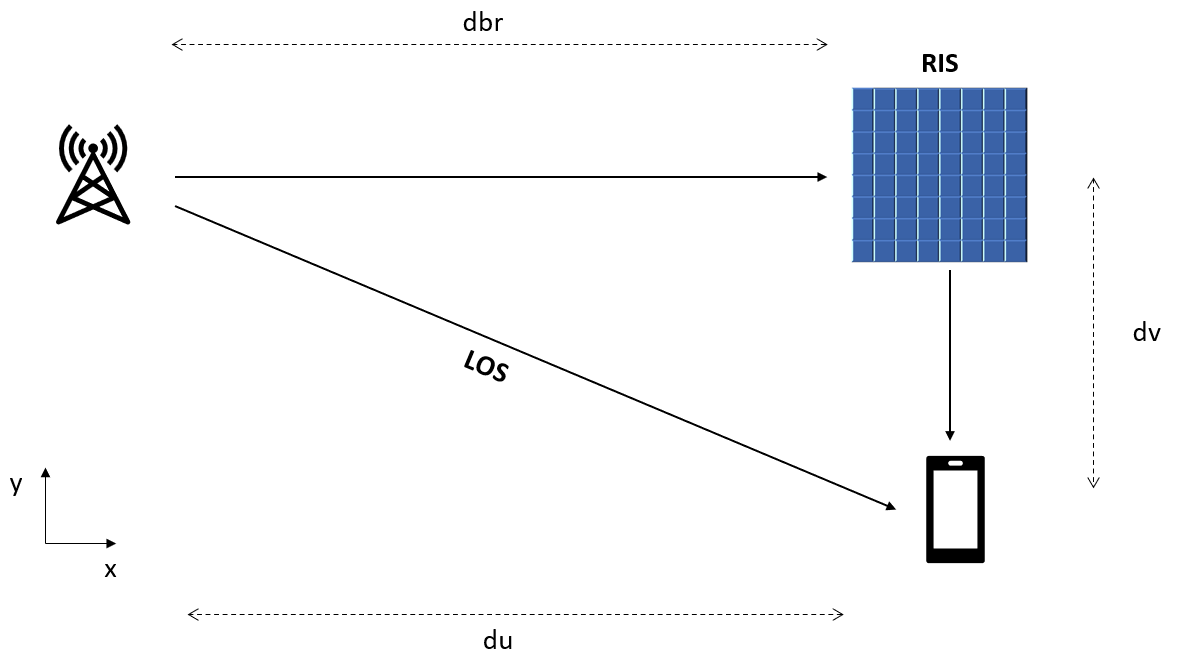
% scene
dbr = 50;
pos_ap = [0;0;0];
pos_ris = [dbr;0;0];
v = zeros(3,1);

du = 50;
dv = -5;
pos_ue = [du;dv;0];

% compute the range and angle of the RIS from the base station and the UE
[r_ap_ris,ang_ap_ris] = rangeangle(pos_ap,pos_ris);
[r_ue_ris,ang_ue_ris] = rangeangle(pos_ue,pos_ris);
For the sake of simplicity, this example uses a single-input-single-output SISO system, i.e., one transmit antenna and one receive antenna. Assume the transmit power is 50 mW and the receiver noise power is -60dBm. The signal is a BPSK signal with a sample rate of 10 MHz.
% signal
fs = 10e6;
x = 2*randi(2,[100 1])-3;
tx = phased.Transmitter('PeakPower',50e-3,'Gain',0);
xt = tx(x);
N0dB = -60-30;

% channel
chanAPToRIS = phased.FreeSpace('SampleRate',fs,'PropagationSpeed',c,'MaximumDistanceSource','Property','MaximumDistance',500);
chanRISToUE = phased.FreeSpace('SampleRate',fs,'PropagationSpeed',c,'MaximumDistanceSource','Property','MaximumDistance',500);
chanAPToUE = phased.FreeSpace('SampleRate',fs,'PropagationSpeed',c,'MaximumDistanceSource','Property','MaximumDistance',500);
RIS-Aided Communication Simulation
First, as a reference, compute the SNR for the direct path
% LOS path propagation
yref = chanAPToUE(xt,pos_ap,pos_ue,v,v);
SNRref = pow2db(bandpower(yref))-N0dB
SNRref = 18.5972
Now let us add the RIS into the environment. As a result, the signal arrives at the receiver through both the LOS path and the reflection path via the RIS. First, check the case without the optimal phase control, i.e., each element in the RIS simply reflects the signal.
risreflector = phased.RISReflector('Surface',ris,'OperatingFrequency',fc);
rcoeff_ris = ones(Nr*Nc,1);
x_ris_in = chanAPToRIS(xt,pos_ap,pos_ris,v,v);
x_ris_out = risreflector(x_ris_in,ang_ap_ris,ang_ue_ris,rcoeff_ris);
ylosris = chanRISToUE(x_ris_out,pos_ris,pos_ue,v,v)+chanAPToUE(xt,pos_ap,pos_ue,v,v);
SNRlosris = pow2db(bandpower(ylosris))-N0dB
SNRlosris =
18.6079
Note that there is little improvement on SNR. This result may be a bit surprising but simply shows that without proper phase control, the reflected signal from an RIS could cancel out the direct path signal. Therefore, it is critical to control the phase of elements in the RIS. Intuitively, you may have guessed that the optimal phase for the RIS is to coherently combine the reflections from all elements, so it arrives at the receiver with the same phase as the direct path signal. This way, the direct path and the reflection path's signal are coherently combined too. To achieve that, you need to have the channel information. There are many algorithms available for channel estimation, but they are beyond the scope of this example. Given the simple scenario in this example, the next code section derives the channel and reruns the simulation with the optimal phase from the RIS.
% channel estimation
stv = phased.SteeringVector('SensorArray',ris);
r_ue_ap = norm(pos_ap-pos_ue);
hd = db2mag(-fspl(r_ue_ap,lambda))*exp(1i*2*pi*r_ue_ap/c);
g = db2mag(-fspl(r_ap_ris,lambda))*exp(1i*2*pi*r_ap_ris/c)*stv(fc,ang_ap_ris);
hr = db2mag(-fspl(r_ue_ris,lambda))*exp(1i*2*pi*r_ue_ris/c)*stv(fc,ang_ue_ris);

% compute optimal phase control
rcoeff_ris = exp(1i*(angle(hd)-angle(hr)-angle(g)));

% rerun simulation
x_ris_in = chanAPToRIS(xt,pos_ap,pos_ris,v,v);
x_ris_out = risreflector(x_ris_in,ang_ap_ris,ang_ue_ris,rcoeff_ris);
ylosriso = chanRISToUE(x_ris_out,pos_ris,pos_ue,v,v)+chanAPToUE(xt,pos_ap,pos_ue,v,v);
SNRlosriso = pow2db(bandpower(ylosriso))-N0dB
SNRlosriso =
28.4933
Now the receiving SNR is greatly improved.
RIS-Aided Communication without LOS
Although the deployment of the RIS can boost the SNR by matching the reflected signal to the direct path signal, the benefit of an RIS really shines when the LOS link is not available. Such cases are not rare in an urban wireless communication scene, and the motion of a mobile user can also make an existing LOS link disappear. Next section simulates such a scenario by removing the direct link from the receiver.
rcoeff_ris = exp(1i*(-angle(hr)-angle(g)));
x_ris_in = chanAPToRIS(xt,pos_ap,pos_ris,v,v);
x_ris_out = risreflector(x_ris_in,ang_ap_ris,ang_ue_ris,rcoeff_ris);
yriso = chanRISToUE(x_ris_out,pos_ris,pos_ue,v,v);
SNRriso = pow2db(bandpower(yriso))-N0dB
SNRriso =
27.9490
You can see from the result that the link quality degrades by only 0.5 dB. This means that the RIS can successfully maintain a communication link without the LOS path. By periodically estimating the link and applying the optimal phase control, the degradation due to the user motion can also be alleviated.
Given this result, it will be of interest to see how the size of an RIS affects the link quality. The curve below shows how the achievable data rate changes as a function of the size of the RIS, where the direct path's data rate is used as a reference. Two things are worth noting from the plot:
An RIS needs to surpass a certain size to be able to improve the overall link quality.
As the number of elements in an RIS increases, it can maintain the link quality with or without the direct path. This is understandable because the larger the RIS, the higher the gain and the less critical the gain from the LOS link.
Ncparam = 5:5:50;
[SNRlosris_param,SNRris_param,SNRlos_param] = helperRISSimulation(xt,Ncparam,chanAPToUE,chanAPToRIS,chanRISToUE,pos_ap,pos_ris,pos_ue,v,fc,c,SNRref);
plot(Ncparam.'*10,log2(1+db2pow([SNRlosris_param;SNRris_param;SNRlos_param])));
legend('LOS+RIS','RIS','LOS');
xlabel('Number of Elements');
ylabel('Data Rate (bps/Hz)')

RIS Placement
With an understanding of the benefit of an RIS, the next section evaluates the deployment strategy of an RIS. The simulation places the RIS at various locations along the x axis and plots the resulting SNR at the UE.
dbrparam = 5:5:50;
SNRris_param = helperRISPlacementSimulation(xt,dbrparam,risreflector,chanAPToUE,chanAPToRIS,chanRISToUE,pos_ap,pos_ue,v,fc,c);
plot(dbrparam,SNRris_param);
xlabel('RIS Position along X (m)');
ylabel('SNR (dB)')
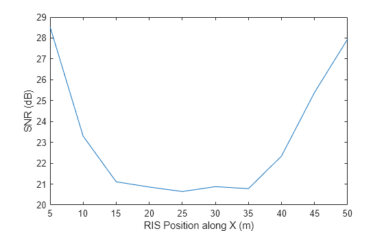
The result shows that to maximize the benefit of an RIS, the RIS should be deployed at a location either close to the base station, as shown on the left side of the curve, or close to the mobile, which corresponds to the right side of the curve.
Summary
This example introduced the basic concept of a reconfigurable intelligent surface and showed how it can be used to improve the propagation environment for future wireless systems.
References
[1] Mohamed A. Elmossallamy, Hongliang Zhang, Lingyang Song, Karim Seddik, Zhu Han, and Geoffrey Li, Reconfigurable Intelligent Surfaces for Wireless Communications: Principles, Challenges and Opportunities, IEEE Trans. on Cognitive Communications and Networking, V9l. 6, No. 3, September 2020
[2] Qingqing Wu, Shuowen Zhang, Beixiong Zheng, Changsheng You, and Rui Zhang, Intelligent Reflecting Surface-Aided Wireless Communications: A Tutorial, IEEE Trans. on Communications, Vol. 9, No. 5, May 2021
Helper Functions
Simulate receiver SNR with RIS
function [SNRlosriso,SNRriso,SNRlos] = helperRISSimulation(xt,Ncparam,chanlos,chanap2ris,chanris2ue,pos_ap,pos_ris,pos_ue,v,fc,c,SNRref)

lambda = c/fc;
Nr = 10;
dr = 0.5*lambda;
dc = 0.5*lambda;

N0dB = -90;
Nparam = numel(Ncparam);
SNRlosriso = zeros(1,Nparam);
SNRriso = zeros(1,Nparam);
for m = 1:Nparam
    release(chanap2ris);
    release(chanlos);
    release(chanris2ue);

    ris = phased.RectangularRIS('Size',[Nr Ncparam(m)],'Spacing',[dr dc],...
        'UnitCell',phased.IsotropicAntennaElement);
    risreflector = phased.RISReflector('Surface',ris,'OperatingFrequency',fc);

    [r_ap_ris,ang_ap_ris] = rangeangle(pos_ap,pos_ris);
    [r_ue_ris,ang_ue_ris] = rangeangle(pos_ue,pos_ris);

    % channel estimation
    stv = phased.SteeringVector('SensorArray',ris);
    r_ue_ap = norm(pos_ap-pos_ue);
    hd = db2mag(-fspl(r_ue_ap,lambda))*exp(1i*2*pi*r_ue_ap/c);
    g = db2mag(-fspl(r_ap_ris,lambda))*exp(1i*2*pi*r_ap_ris/c)*stv(fc,ang_ap_ris);
    hr = db2mag(-fspl(r_ue_ris,lambda))*exp(1i*2*pi*r_ue_ris/c)*stv(fc,ang_ue_ris);


    rcoeff_losriso = exp(1i*(angle(hd)-angle(hr)-angle(g)));
    ylosriso = chanris2ue(risreflector(chanap2ris(xt,pos_ap,pos_ris,v,v),ang_ap_ris,ang_ue_ris,rcoeff_losriso),pos_ris,pos_ue,v,v)+...
        chanlos(xt,pos_ap,pos_ue,v,v);
    SNRlosriso(m) = pow2db(bandpower(ylosriso))-N0dB;

    rcoeff_ris = exp(1i*(-angle(hr)-angle(g)));
    yriso = chanris2ue(risreflector(chanap2ris(xt,pos_ap,pos_ris,v,v),ang_ap_ris,ang_ue_ris,rcoeff_ris),pos_ris,pos_ue,v,v);
    SNRriso(m) = pow2db(bandpower(yriso))-N0dB;

end

SNRlos = SNRref*ones(1,Nparam);
end
Simulate SNR impact with varying RIS locations
function SNRris = helperRISPlacementSimulation(xt,drparam,risreflector,chanlos,chanap2ris,chanris2ue,pos_ap,pos_ue,v,fc,c)

lambda = c/fc;
stv = phased.SteeringVector('SensorArray',risreflector.Surface);
N0dB = -90;
Nparam = numel(drparam);
SNRris = zeros(1,Nparam);
for m = 1:Nparam
    release(chanap2ris);
    release(chanlos);
    release(chanris2ue);

    pos_ris = [drparam(m);0;0];

    [r_ap_ris,ang_ap_ris] = rangeangle(pos_ap,pos_ris);
    [r_ue_ris,ang_ue_ris] = rangeangle(pos_ue,pos_ris);

    % channel estimation
    g = db2mag(-fspl(r_ap_ris,lambda))*exp(1i*2*pi*r_ap_ris/c)*stv(fc,ang_ap_ris);
    hr = db2mag(-fspl(r_ue_ris,lambda))*exp(1i*2*pi*r_ue_ris/c)*stv(fc,ang_ue_ris);

    rcoeff_ris = exp(1i*(-angle(hr)-angle(g)));
    yriso = chanris2ue(risreflector(chanap2ris(xt,pos_ap,pos_ris,v,v),ang_ap_ris,ang_ue_ris,rcoeff_ris),pos_ris,pos_ue,v,v);
    SNRris(m) = pow2db(bandpower(yriso))-N0dB;
end
end