R2022a

New Features, Bug Fixes, Compatibility Considerations

Simulink Fundamentals course

You can now access the self-paced, interactive Simulink® Fundamentals course that teaches you to:

  • Use the Simulink environment.

  • Model continuous and discrete dynamic systems.

  • Organize growing models in subsystems that create visual and functional hierarchy.

  • Componentize models by referencing other models and creating libraries.

  • Optimize simulation performance.

Simulink Fundamentals uses tasks to teach concepts incrementally, such as through a real-life example with a 3D printer. You receive automated assessments and feedback after submitting tasks. Your progress is saved when you exit the course, so you can complete the course in multiple sessions.
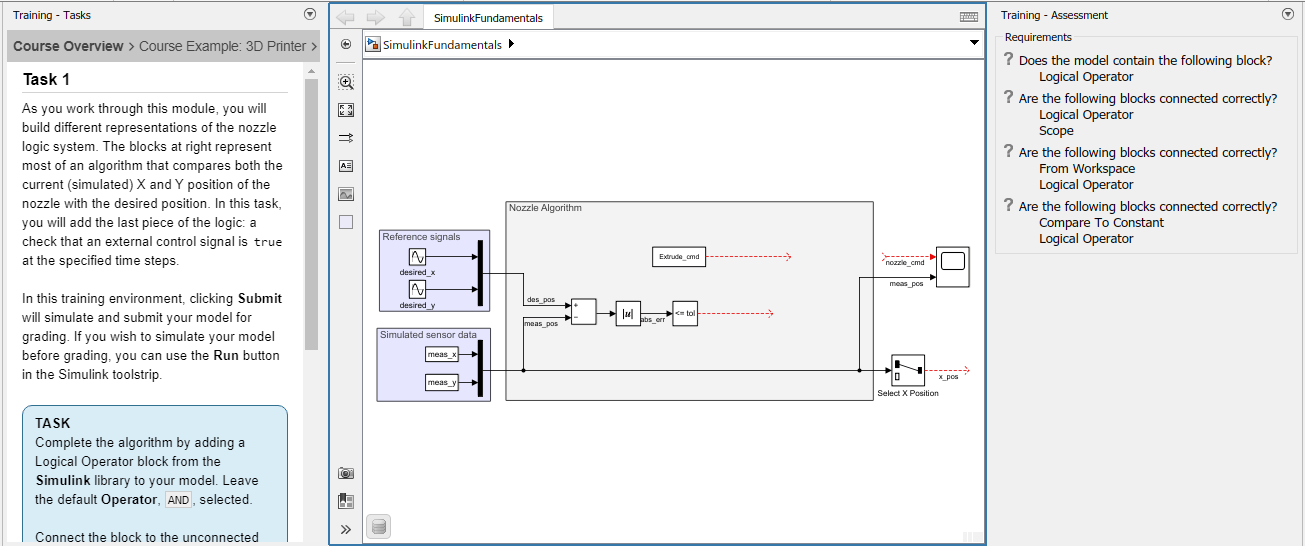
Simulink Fundamentals task

For more information, see Simulink Fundamentals.

Learn tab provides access to in-product trainings

The Simulink Start Page now has a Learn tab that provides access to in-product trainings, such as Simulink Onramp and Simulink Fundamentals.
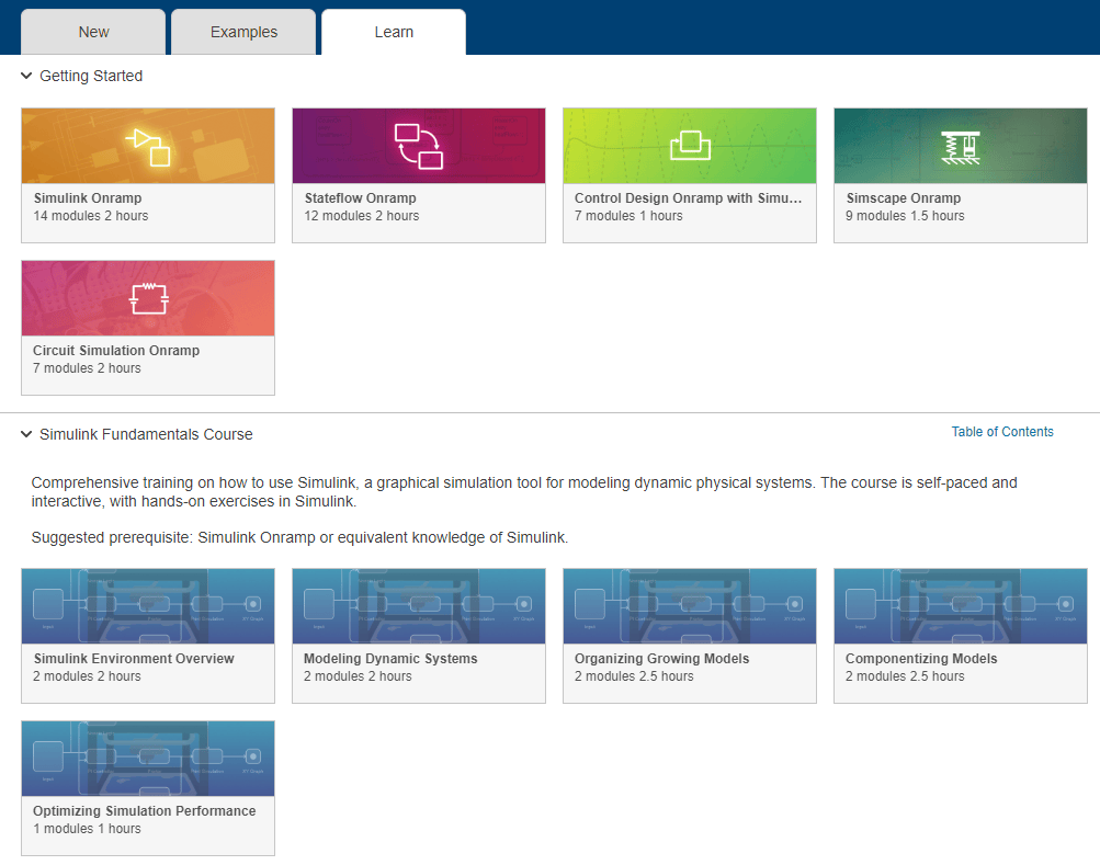
Learn tab of Simulink Start Page

Drop-down menu for Simulink Editor pane interactions

In Simulink Editor panes, a new button to the right of the pane title provides options to undock, minimize, and open help for the pane.

Next to the pane title, a drop-down button provides the option to undock the pane.

When a pane is not docked to the Simulink Editor, the button provides the option to dock and open help for the pane.

When a pane is minimized, the button provides the option to undock, restore, and open help for the pane.

 Compact Boundaries for Simscape Blocks Improve Model Layout and Readability

Simscape™ blocks that have unused space around the block icon and do not have a solid boundary line now get a more compact boundary in block diagrams. This enhancement affects only the block display and enables these improvements:

  • The signal lines pass near the new compact block boundary, which allows better autorouting of lines.

  • Icon, badge, annotation, and action bar for the block appears near the compact boundary of the block. The block background color applies only within the compact boundary, which improves readability.

  • Adjacent blocks align close to each other without overlap, which avoids truncation of content.

For example, see Resistor, Variable Resistor, and Capacitor blocks. The compact boundary improvements do not apply to blocks that have a solid boundary line, for example, PS Ramp and Gear Box blocks.
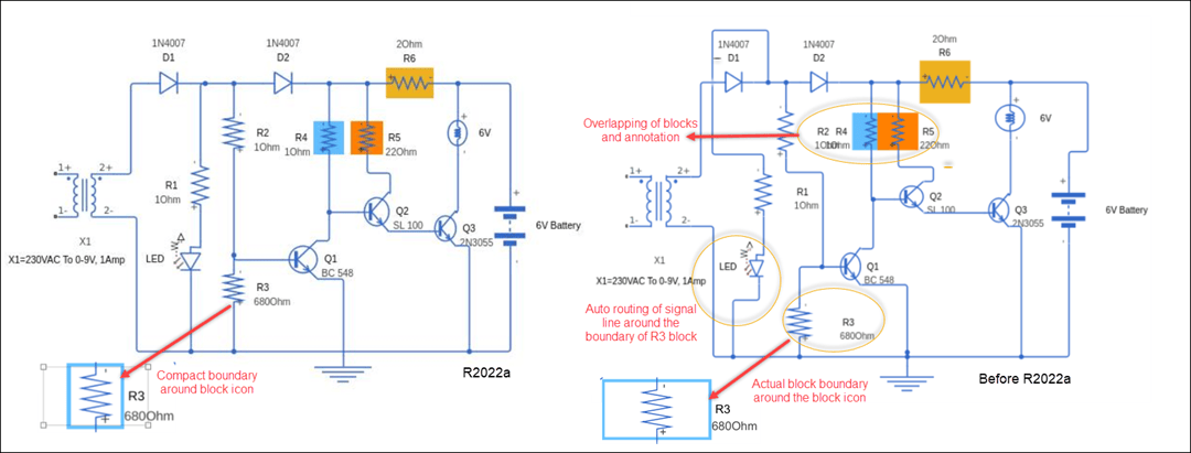
Compact boundary for Simscape blocks

 Compatibility Considerations

If you open a model created using a previous version of Simulink in R2022a and the model has compact blocks, then background color for such blocks is applied only within the compact boundary.

If you save a model created in R2022a to a previous version, the compact boundaries will be removed. Adjacent blocks can overlap, background color is applied to the complete block boundary, and signal lines can appear as passing through the block.

Highlight reduced nonvirtual blocks

You can now highlight nonvirtual blocks that are removed to reduce execution time during model simulation and code generation. To enable this functionality, select the model configuration parameter Block reduction. For more information, see Block reduction.
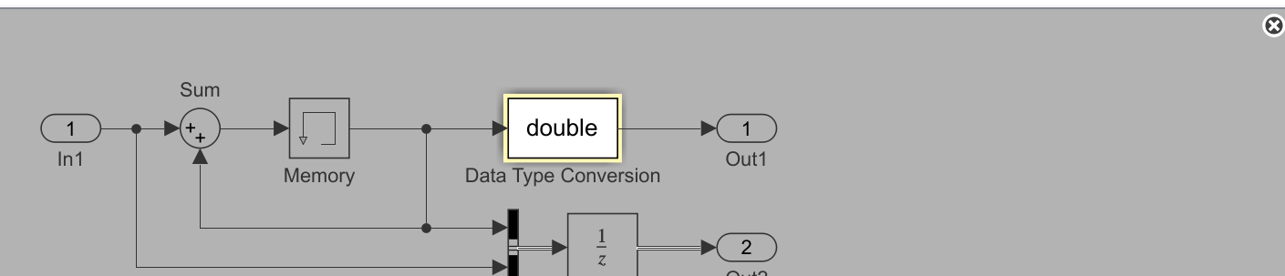
Simulink canvas with a simple model. Background is in grey, and one block, a Data Type Conversion block, is highlighted with a yellow border and white background. In the upper-right corner of the canvas, there is a circle containing an X.

Add State Reader, State Writer, and Parameter Writer blocks from Simulink toolstrip

You can now add State Reader, State Writer, and Parameter Writer blocks to your model directly from the Simulink toolstrip.

To add a State Reader or State Writer block, highlight by clicking on a block that has a state that the State Reader or State Writer block can read or write to. On the current block tab of the toolstrip, click Reader-Writer and select State Reader Block or State Writer Block from the list. A State Reader or State Writer block appears on the canvas with the State owner block parameter set to the block that was highlighted. The method of adding a State Reader or State Writer block by right-clicking and dragging a state owner block is no longer supported starting in R2022a.
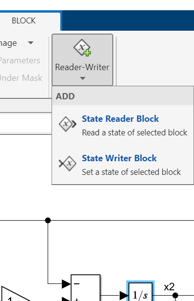
Excerpt from Block tab of Simulink Toolstrip showing button labeled "Reader-Writer", with dropdown menu showing "State Reader Block" and "State Writer Block" options. An Integrator block is highlighted on the canvas.

Note

Depending on the type of block you highlight, the current block tab of the toolstrip might be labeled with the name of the highlighted block, for example, Constant, or it might be labeled Block.

Similarly, to add a Parameter Writer block, highlight by clicking on a block with a parameter that the Parameter Writer block can write to. Then, on the current block tab of the toolstrip, click Parameter Writer. A Parameter Writer block appears on the canvas with the Parameter owner block parameter set to the block that was highlighted.
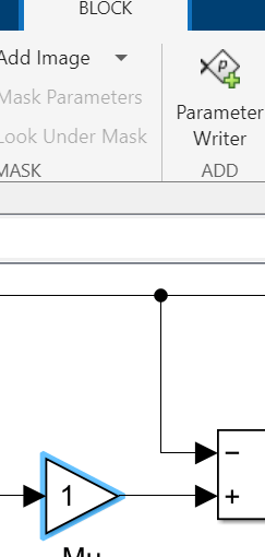
Excerpt from Block tab of Simulink Toolstrip showing button labeled "Parameter Writer". A Gain block is highlighted on the canvas

If you highlight a block that has both a state that the State Reader or State Writer block can read or write to and a parameter that the Parameter Writer block can write to, on the current block tab of the toolstrip, click Reader-Writer. Select Parameter Writer Block, State Reader Block, or State Writer Block from the list.
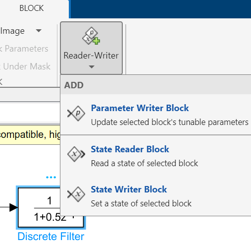
Excerpt from Block tab of Simulink Toolstrip showing button labeled "Reader-Writer", with dropdown menu showing "Parameter Writer Block", "State Reader Block", and "State Writer Block" options. A Discrete FIR Filter block is highlighted on the canvas.

After you add a State Reader, State Writer, or Parameter Writer block, cut and paste it to move it to the desired location within the model hierarchy.

Related block highlighting for Variant Connector and Parameter Writer blocks

Starting in R2022a, selecting a primary Variant Connector block, a Parameter Writer block, or a block related to either of them, highlights all blocks that are related to the selected block.

A primary Variant Connector block and all nonprimary Variant Connector blocks with the same Connector Tag as that primary block constitute a set of related blocks.
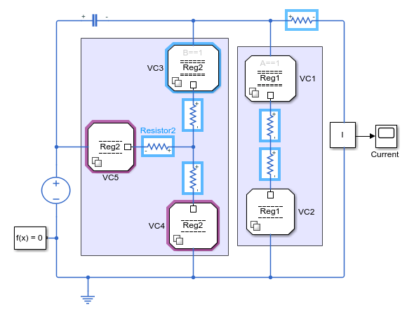
Model of an electric circuit, in which a primary Variant Connector block is selected, and its two related nonprimary Variant Connector blocks are highlighted

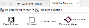
A Parameter Writer block and the parameter owner block of the value that it writes constitute a set of related blocks.
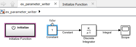
Model in which a Constant block is selected, and an Initialize Function block is highlighted

Contents of the Initialize Function block, containing a highlighted Parameter Writer block

When a related block is highlighted, blocks in the current model that contain the related block are also highlighted. For example, an Initialize Function block is highlighted when it contains a Parameter Writer block that is related to the selected block.

Port toolbar menu customizations to custom tab in toolstrip

A custom toolbar menu in the Simulink Editor can now be converted into a toolstrip tab using the slConvertCustomMenus command.

Converting a custom toolbar menu creates a toolstrip tab with a single section, which is populated by the converted menu items from the toolbar menu. List items from the menu are converted into push buttons, and list items with pop-up lists are converted into drop-down buttons.
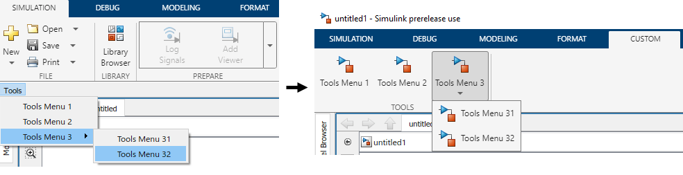
A custom toolbar menu on the left labeled Tools has two list items without pop-up lists and one list item with a pop-up list. The converted toolstrip tab is on the right and shows a single tab labeled TOOLS that has two push buttons and one drop-down button.

The toolbar menu is not automatically deleted during the conversion. You can remove it by commenting out or deleting the corresponding addCustomMenuFcn call in the sl_customization file.

Any functionality that custom tabs do not support is ignored during the conversion. However, you can edit the generated tab. For more information, see Create Custom Simulink Toolstrip Tabs.

View and trace callbacks

You can view and trace all the callbacks executed in a model. Enable the option Log Callbacks to record all callbacks executed in the model. To view the callback report, go to Diagnostics > Callback Tracer.

For more information, see View and Trace Callbacks in Model

Use modelfinder to find Simulink models

Using modelfinderyou can:

  • Find models that match the specified string in model name, blocks, annotations, or description.

    You can also find models that matches a specific search string and contains specified blocks. For example, you can search models that matches the search string dc motor in it and contains pulse generator and pi controller blocks.

  • Index models in a specific path. Register or unregister a folder to include all the models in that folder so that they appear in the modelfinder search results.

For more information, see modelfinder|modelfinder.registerFolder | modelfinder.unregisterFolder

Unified breakpoint list in the Simulink Editor for debugging

In R2022a, you can use the new breakpoint list in the Simulink Editor to manage breakpoints set in a model. The unified breakpoint list includes useful metadata and tools for navigating to, modifying, organizing, sorting, and searching the breakpoints in the list. The breakpoint list includes different types of breakpoints that you can set, for example, Stateflow® and MATLAB® Function blocks.

 Toolstrip-based UI for Model Advisor​​​​

The Model Advisor user interface now includes simplified toolstrip with new features.

  • Filter Checks - Filters the checks based on their respective result statuses, such as Failed, Passed, Justified.

  • Justify - Justify the violations. Justifications allow you to add a rationale for violations observed during Model Advisor analysis. For more information, see Justify Violated Blocks from the Model Advisor Check Analysis (Simulink Check).

  • Fix - Fixes the violations by setting the violated parameter values to recommended values.

  • Reports - Export Model Advisor analysis reports in HTML, PDF, and DOCX formats.

  • Manage Configurations - Create, load, restore, and associate configurations in simple workflows.

This table describes the changes to the menu items in the Model Advisor:

Previous UI ElementNew UI ElementDescription of the Change
Run Selected ChecksRun ChecksNo change in functionality. Use this button to run selected checks.
Settings > (options)Open > (options)Some older options are no longer available. Use this button to open or customize Model Advisor Configuration Editor.
Generate Report…Report > (options)No change in functionality. Use this button to generate the Model Advisor analysis report in HTML format. Use the drop-down option to selectPDF or WORD.
Configure Hidden input parametersConfigure input parameters in Model Advisor Configuration EditorConfigure hidden input parameters was a hyperlink in the check window. In R2022a, you can now click the Configure input parameters in Model Advisor Configuration Editor icon ().
Edit > Send Check IDs to WorkspaceRight-click on any check, and select Send Check IDs to Workspace.Use this option to send check IDs to workspace.
Edit > Send Instance IDs to WorkspaceRight-click on any check, and select Send Instance IDs to Workspace.Use this option to send instance IDs to workspace.

This table describes the navigation options removed from Model Advisor:

Navigation Options Removed
Settings > Treat as referenced model
Settings > Preferences
Edit > Reset
Switch to Model Advisor Dashboard
Run Checks in Background
Highlighting check results
Highlight exclusion results
Highlighting

For more information, see Run Model Advisor Checks and Review Results (Simulink Check).

 Functionality being removed or changed

Toolbar menu customization will be removed

Still runs

Toolbar menu customization will be removed in a future release. Use custom toolstrip tabs instead.

Custom tabs better integrate into the Simulink Toolstrip. Menu items that were previously hidden within the toolbar menus are directly available on custom tabs. For information on custom tabs, see Create Custom Simulink Toolstrip Tabs.

To migrate your toolbar menu customization, see Port toolbar menu customizations to custom tab in toolstrip.

New simulation status during initialization of fast restart simulation

Behavior change

Starting in R2022a, fast restart simulations clearly indicate when the simulation is restarting. While fast restart is in progress, the simulation status becomes Restarting, and the Simulink Editor becomes frozen like it is during model compilation and initialization.

In previous releases, the Simulink Editor and simulation status did not give an indication that fast restart was in progress. The table summarizes updates to messages in the Simulink Editor and to the SimulationStatus model configuration parameter value.

Simulation Status Information while Fast Restart is in ProgressBefore R2022aStarting in R2022a

Simulation status message in the bottom left of the Simulink Editor

Fast Restart (Ready)

Restarting

Model status in the bottom right of the Simulink Editor before simulation starts

Initialized

Compiled

SimulationStatus configuration parameter value

compiled

restarting

Models or scripts that conditionalize behavior based on the value of the SimulationStatus parameter might behave differently or give an error during fast restart simulations.

Unconnected block input ports, block output ports, and lines do not warn by default

Behavior change

Starting in R2022a, new models do not warn by default for unconnected block input ports, block output ports, or lines.

To enable the warnings, change the related configuration parameter values. On the Modeling tab, click Model Settings. In the Configuration Parameters dialog box, open the Diagnostics > Connectivity pane.

Simulation Analysis and Performance

Local solver

Starting in R2022a, you can speed up simulation in model references by using the local solver to choose different tradeoffs for different sections of a model, depending on your needs. This new feature lets you choose less expensive solvers for slower models.

Zero-Crossing detection using Fixed-Step Solver

Starting in R2022a, you can use fixed-step solvers to detect zero-crossings and locate events based on continuous zero-crossing signals that register events.

Change visualization for a subplot more easily in the Simulation Data Inspector

Starting in R2022a, the subplot menu and the context menu for subplots in the Simulation Data Inspector include an option to change the visualization for that subplot. Previously, to change the visualization for a subplot, you could only use the Visualization Gallery in the Simulation Data Inspector.
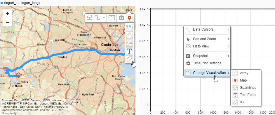
Map with the subplot menu open and the Change Visualization option expanded next to a time plot with the context menu open and the Change Visualization option expanded.

Changing the visualization for several subplots in the Simulation Data Inspector is also easier. The Visualization Gallery now remains open until you close it, and you can freely position the window within the plot area.

XY, sparklines, and map visualization enhancements

Several visualizations you can use in the Record block and Simulation Data Inspector have enhancements in R2022a:

  • When you add a trend line to an XY plot, the trend line now has a tooltip that shows:

    • The series and signals to which the trend line was fitted.

    • The x- and y-coordinates for the point nearest the pointer.

    • The trend line equation and R-squared value.

      Polynomial data plotted on an XY plot in the Simulation Data Inspector with the trend line tooltip visible.

  • The legend for the XY plot has a tooltip that indicates which run contains the plotted signal data.
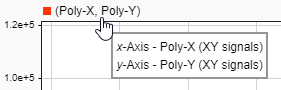
    Legend for an XY plot in the Simulation Data Inspector with the legend tooltip visible.

  • Sparklines plots now show tick labels for the time axis only on the last sparkline with a visible time axis. You can control whether tick labels are shown for all sparklines or only the last sparkline using the Visualization Settings.
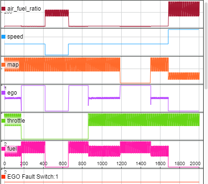
    Sparklines plot that displays data from several signals. Time axis labels are shown only on the last sparkline with a visible time axis.

  • Maps now show a legend that indicates which signals provide the latitude and longitude data for the plotted route. The legend has a tooltip that indicates which run contains the plotted data.
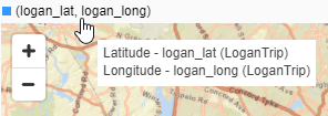
    Legend for a map in the Simulation Data Inspector with the legend tooltip visible.

Interactive comparison report enhancements

Interactive comparison reports created using the Simulation Data Inspector have these enhancements:

  • You can sort comparison results in the report by name, absolute tolerance, relative tolerance, maximum difference, and result.

  • The generated comparison report reflects the grouping in the Simulation Data Inspector at the time the report was generated. For example, when you group the results by data hierarchy, the results are grouped by data hierarchy in the generated report.

External debugger integration for debugging custom C/C++ code​

You can now debug your custom C/C++ code from within Simulink by launching an external debugger and setting breakpoints in your custom code. The following debuggers are supported:

  • On Windows®, Microsoft® Visual Studio® debugger

  • On Linux®, GNU® Data Display Debugger (DDD)

  • On macOS, LLDB Debugger (LLDB)

To launch the external debugger, on the Debug tab of the Simulink toolstrip, in the Breakpoints section, click the arrow to the right of the Add Breakpoint button. From the menu, select Set Breakpoints in Custom Code.
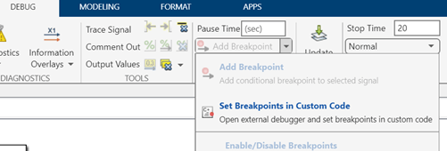
Excerpt from Debug tab of Simulink Toolstrip. The 'Add Breakpoint' dropdown menu is open, and 'Set Breakpoints in Custom Code' is the second option on the menu.

For more information, see Debug Custom C/C++ Code.

Parameter Combinations in Multiple Simulations panel

In R2022a, you can use Parameter Combinations in the Multiple Simulations panel of the Simulink Editor for workflows with multiple simulations, such as Monte-Carlo simulations and parameter sweeps. Parameter Combinations allows you to create sequential and exhaustive combinations of parameters, specify value ranges, and run simulations with these combinations

 Functionality being removed or changed

Simulink.sdi.setRunOverwrite function has been removed

Errors

In R2022a, the Simulink.sdi.setRunOverwrite function has been removed. Using the function in a script causes an error.

In R2018b, the Simulink.sdi.setRunOverwrite function was replaced. Since R2018b, the Simulink.sdi.setRunOvewrite function has had no effect on the Simulation Data Inspector, and scripts that use the function have generated a warning.

To retain data for only a single run in the Simulation Data Inspector, use the Simulink.sdi.setAutoArchiveMode function and the Simulink.sdi.setArchiveRunLimit function. Configure the Simulation Data Inspector to automatically move runs into the archive, and set the archive run limit to 0.

Simulink.sdi.setAutoArchiveMode(true);
Simulink.sdi.setArchiveRunLimit(0);

For more information about configuring the Simulation Data Inspector archive, see Archive Behavior and Run Limit.

Component-Based Modeling

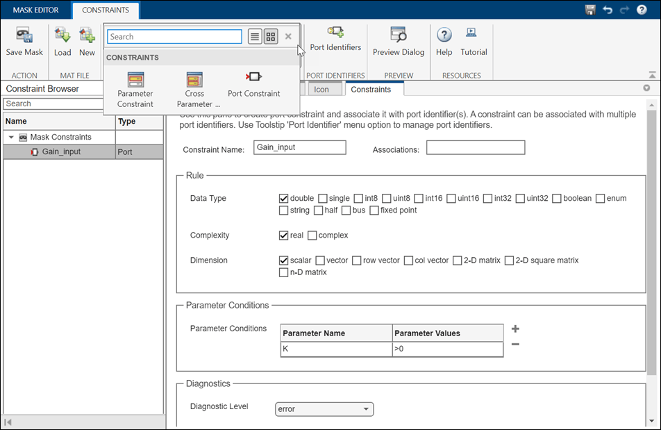
Mask Editor streamlines masking workflow for Parameter Constraint, Port Constraint, and Parameter Promotion

In R2022a, the Mask Editor has new capabilities that enable you to perform masking operations with fewer clicks.mask editor 2.0
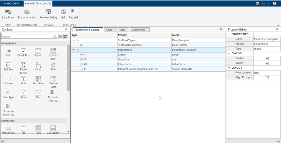
This table lists the new and improved capabilities in Mask Editor.

New and Improved Mask Editor Features

FeatureImproved or New?
Context-based tool strip for easy navigation – The menu options appear based on context. For example, the options for Parameter Constraint, Cross Parameter Constraint, and Port Constraint appear only when you select the Constraint tab.New
Integrated view of initialization code and callback code – You can view the mask initialization code and callback code in a single integrated MATLAB Editor. Previously, the initialization code and callback code were in different locations. The Mask Editor code functionalities are like those in the MATLAB Editor, with some limitations. For example, the autocomplete functionality is supported, but you cannot set a breakpoint in your code.New
Upload image within Mask Editor – You can set an image for the masked block icon within the Mask Editor. New

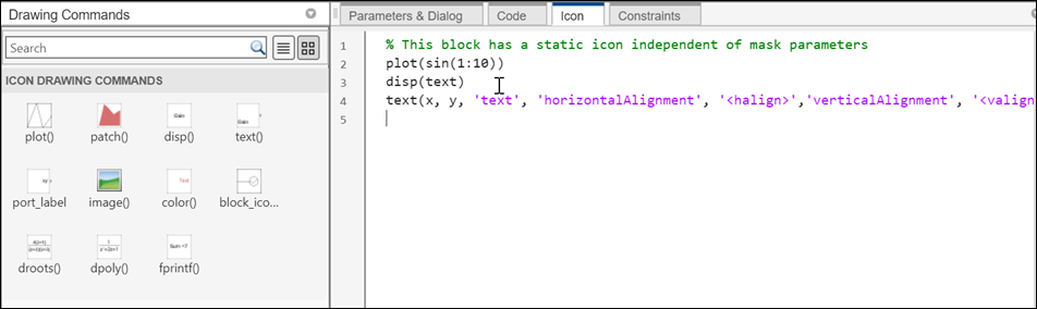
Icon drawing commands – The skeleton for drawing commands appears when you click the commands.

icon drawing commands

New

New Constraint Manager with support for port constraints – Constraint Manager is integrated inside the Mask Editor.

constraint manager

New

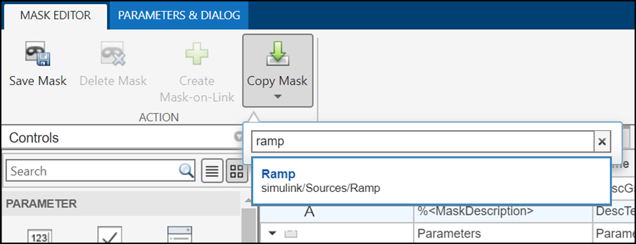
Copy mask definitions from Simulink library blocks – Search for the desired block and click Copy Mask to import the mask definition from an existing block.

copy mask

New

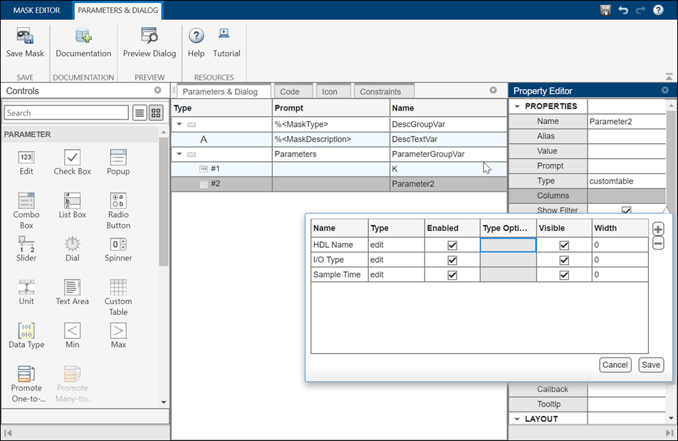
Enhanced Property Editor for parameters – The new Property Editor allows you to set values for parameters such as Tree, LUT Widget, Tunable Popup, Custom Table, and Text Area. For example, you can use the Property Editor to specify the column properties of a custom table. Previously, you had to set values in text form using delimiters.

property editor

Improved

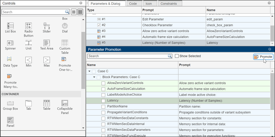
Enhanced Parameter Promotion workflow – You can now promote parameters in fewer steps. An integrated view allows you to see all promotable parameters of a block. You can select multiple parameters to promote in the case of many-to-one parameter promotion. For more information, see Promote Block Parameters on a Mask

parameter promotion

Improved

Specify port constraints on masked block

Starting in 2022a onward, you can specify constraints on the input and output ports of a masked block. The port attributes are checked against the constraints when you compile the model.

For more information, see Validate Input and Output Port Signals Using Port Constraints.

Bus Editor enhancements

The Bus Editor loads faster and has an updated interface for creating, modifying, and managing bus objects.

  • A toolstrip provides easy access to actions.

  • A Sources pane provides the available object sources.

  • An interactive table displays editable information about the objects, such as hierarchy and properties.

  • A Property Inspector pane lets you focus on one object at a time and edit its properties.
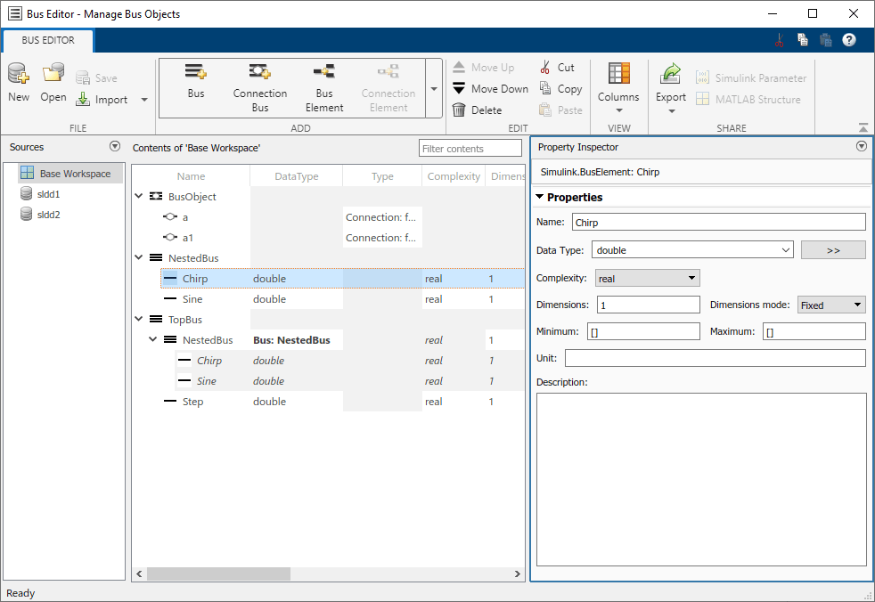
Updated Bus Editor appearance

For more information, see Bus Editor.

Message Triggered Subsystem and Message Polling Subsystem blocks: Process messages by executing subsystem when message is available

The new Message Triggered Subsystem and Message Polling Subsystem blocks are each a type of conditionally executed subsystem that uses messages as the control signal. The information contained in the messages is accessible inside the subsystem.

  • A Message Triggered Subsystem block executes whenever a message is available at the control port, independent of block sample time.

  • A Message Polling Subsystem block pulls messages from a queue periodically based on its sample time and executes only when a message is available.
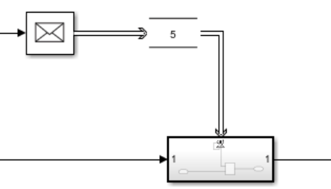
Simulink canvas with Message Send block connected to Queue block which is connected to control port of Triggered Subsystem block

A Message Triggered Subsystem block can be used to define an independent function at the root level of an export-function model. See Export-Function Models Overview.

For more information about the Message Triggered Subsystem and Message Polling Subsystem blocks, see Message Triggered Subsystem and Using Message Polling and Message Triggered Subsystems.

Reinitialize ports and Reinitialize Function block: Reinitialize referenced model or subsystem states during simulation

Starting in R2022a, you can reinitialize the states of the blocks inside a referenced model or subsystem at any time during model simulation. Sending a function-call signal to a reinitialize port of the Model block or the Subsystem block creates a reinitialize event that implicitly initializes the states of all blocks within the Model or Subsystem block.
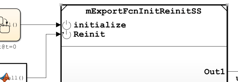
Simulink canvas with a Model block displaying an Initialize port driven by a Stateflow chart and a Reinitialize port driven by a MATLAB Function block

To add a reinitialize port to a referenced model or a subsystem, place a Reinitialize Function block inside the referenced model or subsystem. Then, select the Show model reinitialize ports check box in the Model block parameters dialog or the Show subsystem reinitialize ports check box in the Subsystem block parameters dialog. The Model or Subsystem block displays a reinitialize port, indicated by the Reinit icon icon.

By customizing the contents of a Reinitialize Function block, for instance by using State Writer and Parameter Writer blocks, you can configure a reinitialize event to explicitly override specified states in a referenced model or subsystem in addition to implicitly initializing all states in the referenced model or subsystem. See Reinitialize States of Blocks in Subsystem.

A reinitialize event can be used to initialize states of blocks inside nested subsystems or referenced models and to initialize certain types of blocks that are not affected by an Enabled Subsystem block reset.

You can place multiple Reinitialize Function blocks inside a referenced model or subsystem. In this case, Simulink creates a reinitialize port for each Reinitialize Function block, with each port name corresponding to the Event name of the reinitialize event as specified in the Event Listener block inside the Reinitialize Function block.

Function ports and port-scoped Simulink Function blocks: Call and define functions across peer models

Starting in R2022a, Simulink models can have function ports through which one referenced model calls a function defined in a second referenced model. A model can issue a function call through an invoking function port created by a Function Element Call block to invoke a function defined in another model using a port-scoped Simulink Function block and exported through an exporting function port created by a Function Element block. You can use function ports to model client and server components in a distributed service architecture as well as to facilitate data sharing using a functional interface between component models. See Call Simulink Functions in Other Models Using Function Ports.

Code reuse support in code generation

In previous releases, code generated from Simscape models did not support code reuse. This limitation has now been removed.

Use the new match filter with find_system to find both active and inactive blocks in a model

You can use the built-in match filter, Simulink.match.allVariants(), with the find_system function to find all blocks in a variant model regardless of whether the block is active or inactive due to variants.

For more information, see MatchFilter.

Find variant control variables used by variant parameters

Starting in R2022a, the import control variables operation in Variant Manager and the Simulink.VariantManager.findVariantControlVars method find variant control variables used by variant parameters (Simulink.VariantVariable) that are accessible to the model. See, findVariantControlVars.

Compile code conditionally for all variant parameter values with different dimensions

You can generate code for active and inactive values of variant parameters that have different dimensions. All other attributes, such as data type and complexity, must be the same across all choices of a variant parameter.

When you generate code for variant parameters with different dimensions, with the activation time of the associated variant control variable object to code compile, Embedded Coder® generates code for active and inactive values of variant parameters. The code contains variant parameter definitions and an autogenerated dimension identifier in C preprocessor conditionals #if and #elif. The C preprocessor conditionals enable you to conditionally compile the code for a given active value of a variant parameter. You do not need to regenerate the code every time you change the value of the variant control variables that are associated with variant parameters. For more information on conditionally compiling code, see Compile Code Conditionally for all Values of Variant Parameters with Same and Different Dimensions.

Previously, if a variant parameter had values with different dimensions, you could generate code only for the active values. You had to regenerate the code every time you changed the value of the variant control variable before compiling the code.

Consider this model.
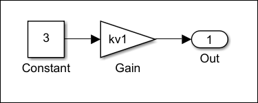
Variant parameters with choice values having different dimensions in a Simulink model

In this model, the Gain parameters of the Gain blocks are set to the variant parameter kv1.

  1. In the MATLAB Command Window, define kv1 as follows. kv1 has values with different dimensions, and the variant activation time of the associated variant control variable object V is set to code compile. Set the storage class of kv1 with exported data scope to generate a code that reuses the variant parameter values that you specified in the model. You can choose to generate a code that imports variant parameter values and its dimensions from external code prior to code compilation by setting the storage class with imported data scope. For more information, see described in Choose Storage Class for Controlling Data Representation in Generated Code (Embedded Coder). In this example, the storage class of the variant parameters is set to ExportedGlobal (Embedded Coder).

    % exported parameters
    spec = Simulink.Parameter();
    spec.CoderInfo.StorageClass = 'ExportedGlobal';
     
    % variant parameters
    choice1 = 'V == 1';
    choice2 = 'V == 2';
    choice3 = 'V == 3';
    kv1 = Simulink.VariantVariable('Choices', {choice1, [1, 2, 3, 4], choice2,
     [1, 2, 3, 4, 5], choice3, [1, 2, 3, 4, 5, 6]},'Specification', 'spec');
    
    % variant control variable
    V = Simulink.VariantControl('Value', 1, 'ActivationTime', 'code compile');

  2. Generate the code using Embedded Coder. The code that you generate contains the variant parameter definition section that has active and inactive values of kv1 that you specified in the model. The code also contains the dimension identifier kv1_dim0 to store the dimensions of variant parameter values across the model.

    //mVPrmVariableDim.c
    #if V == 1
    real_T kv1[kv1_dim0] = { 1.0, 2.0, 3.0, 4.0 };
    
    #elif V == 2
    real_T kv1[kv1_dim0] = { 1.0, 2.0, 3.0, 4.0, 5.0 };
    
    #elif V == 3
    real_T kv1[kv1_dim0] = { 1.0, 2.0, 3.0, 4.0, 5.0, 6.0 };
    #endif
    
    //rtw_variant_dims.h
    /* Definition for custom storage class: Define */
    #if V == 1
    #define kv1_dim0                       4                                                  
    #elif V == 2
    #define kv1_dim0                       5                                                  
    #elif V == 3
    #define kv1_dim0                       6                                                  
    #endif                             
    

    When you compile this code, the compiler evaluates the #if and #elif conditions to determine the active values and dimension of variant parameters based on the value of the variant control variable V that you provide as an input to the compiler. If you specify the value of V as 1, the condition V == 1 evaluates to true, and the values enclosed in V == 1 becomes active during code compilation. You can then specify a different value for V and recompile the same code for any other active value of kv1.

Reuse, control representation, and import variant parameter values in generated code using Simulink.Parameter variables

You can specify Simulink.Parameter variables as values in variant parameters. Using Simulink.Parameter variables allows you to share values among multiple variant parameters, separate values from their data types and other properties, and control the appearance, placement, definition, and declaration of variant parameters values in the generated code. Simulink.Parameter variables help you to import variant parameter values from external code at the beginning of code compile, simulation-loop, and model startup phases of simulation and code generation workflows based on the activation time you specify. For more information, see Stages to Set Active Choices in Variant Blocks and Variant Parameters. When you use Simulink.Parameter variables as values in a variant parameter, corresponding properties of all the Simulink.Parameter variables must be the same. Only the values of Simulink.Parameter variables can vary.

Previously, you could specify only numeric values in variant parameters.

Consider this model.
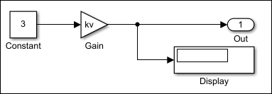
Simulink model with Simulink.Parameter objects as choice values in variant parameters

In this model, the Gain parameter of the Gain block is set to the variant parameter kv.

  1. In the MATLAB Command Window, define kv as follows. kv has the two values kv_hatchback and kv_sedan of Simulink.Parameter type, and the storage class is set to ImportedExtern.

    % imported parameters
    kv_hatchback = Simulink.Parameter(3);
    kv_sedan = Simulink.Parameter(6);
    kv_hatchback.CoderInfo.StorageClass = 'ImportedExtern';
    kv_sedan.CoderInfo.StorageClass = 'ImportedExtern';
    
    % variant parameters
    kv = Simulink.VariantVariable('Choices', {'V == 1', 'kv_hatchback',
     'V == 2', 'kv_sedan'});
    

  2. Define a variant control variable object V with the value set to 1 and the activation time set startup.

    V = Simulink.VariantControl('Value', 1, 'ActivationTime', 'startup');

  3. Generate the code using Embedded Coder or Simulink Coder™. The code is generated as follows.

    //vPrmImported_private.h
    extern real_T kv_hatchback;                    
    extern real_T kv_sedan;
    
    //vPrmImported.c
    void vPrmImported_initialize(void) {
    if (V == 1) {
        mVPrmImported_P.kv = kv_hatchback;
      } else if (V == 2) {
        mVPrmImported_P.kv = kv_sedan;
      }
    }
    

    The initialize function of the generated code is executed at the model startup phase to determine the active value of kv based on the variant condition that evaluates to true. If the condition V == 1 evaluates to true, kv_hatchback is active. If V == 2 evaluates to true, kv_sedan is active. The generated code imports active values from external code at model startup.

For more information, see Reuse Variant Parameter Values from Handwritten Code Using Simulink.Parameter Variables.

Use enumerated values to improve code readability of variant blocks and variant parameters with startup activation time

You can associate enumerated type of values for the variant control variables with startup activation time. Enumerated types improve code readability and simplify the generated code by giving descriptive names to integers used as variant control values in variant control variable objects. For more information, see Enumerated Types To Improve Code Readability of Variant Control Variables of Variant Blocks and Improve Code Readability of Variant Parameters Using Enumerated Types.

Only enumerations that defined using these techniques are supported:

  • Using the function Simulink.defineIntEnumType

  • By subclassing one of these built-in classes:

    • Built-in integer data types int8, int16, int32, uint8, or uint16

    • Simulink.IntEnumType

These enumerations are also supported when permanently stored in a Simulink data dictionary. See Enumerations in Data Dictionary.

Mask parameter enhancements

Starting in R2022a, you can specify the Image and Value Type for the Data Type parameter. You can also have an embedded browser in the mask dialog by specifying HTML Text as Text Type for the Text Area parameter.

Retrieve list of options and evaluated value of a parameter

Starting R2022a, you can retrieve the list of options for a parameter, Simulink object, block diagram, and annotations using the get_param keyword options. You can also access the evaluated value of a masked parameter using get_param with the keyword value.

Use this syntax to get the list of options:

get_param(<block_path>,’options@<parameter_name>’);

Use this syntax to get the evaluated value is:

get_param(<block_path>,’value@<parameter_name>’);

Here, block_path is the block, parameter_name is the name of the parameter on the block whose list of options or evaluated value is to be retrieved.

For more information, see get_param

Constraint Manager integrated with Mask Editor

The Constraint Manager is now integrated inside the Mask Editor. The workflow for sharing constraints is simplified, and you can specify constraints for the input and output ports of blocks.

  • In the current shared constraint workflow, the Constraint Manager is opened in a separate window, and you must create a constraint, save it in a MAT file, and associate the file name with the parameter. Now, you can create or load a MAT file, define constraints or modify existing ones, and associate constraints with parameters within the Mask Editor. The Constraint Browser allows you to manage shared constraints.
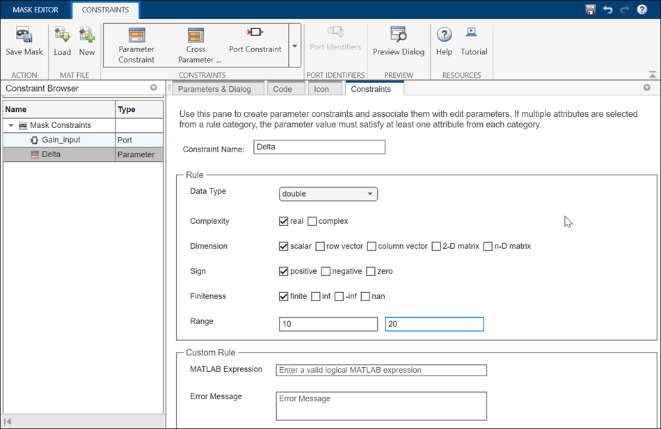
    constraint manager

  • You can use port constraints to specify constraints on the input and output ports of a masked block. The port attributes are checked against the constraints when you compile the model.port constraint

Control Subsystem Reference programmatically

Variable-size signals in array of buses

Starting in R2022a, signals of a bus type containing variable-size signals can form an array of buses, and an array of buses can be a variable-size signal. See Variable-Size Signal Basics and Group Nonvirtual Buses in Arrays of Buses. Support for such signals is limited to normal mode simulation, and not all blocks are supported.

 Designation of export-function model

Starting in R2022a, Simulink allows you to explicitly designate a model as an export-function model. See Export-Function Models Overview. Previously, Simulink attempted to determine whether or not a model was an export-function model by analyzing the contents of the model.

After you designate a model as an export-function model, Simulink performs compile-time checks to warn you if the model does not meet export-function model requirements.

Simulink displays a Badge showing "f()" badge in the lower-left corner of the canvas to indicate that a model is designated as an export-function model.

If you load a model that was created and saved in a prior release, Simulink designates the model as an export-function model if the model meets the requirements to be an export-function model. In some cases, you may need to manually designate such a model as an export-function model.

For more information, see Designating an Export-Function Model.

Redesigned Simulation Target Pane of Model Configuration Parameters

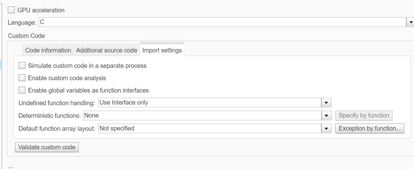
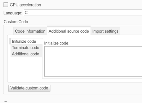
The Simulation Target pane of the Model Configuration Parameters dialog is changed for R2022a. The parameters that pertain to custom code are now together in one section of the dialog, which is organized into three tabs: Code information, Additional source code, and Import settings. Clicking on a tab shows the parameters that are listed under that tab and hides the contents of the other two tabs.

Some of the parameters have new names, and two parameters, Compiler flags and Linker flags, both found on the Code information tab, are new for R2022a.

In the Compiler flags field, you can enter any additional compiler flags to be added to the compiler command line when your custom code is compiled.

In the Linker flags field, you can enter any additional linker flags to be added to the linker command line when your custom code is linked.
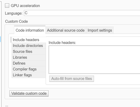
Code information tab of Simulation Target pane of Model Configuration Parameters dialog

Additional source code tab of Simulation Target pane of Model Configuration Parameters dialog

Import settings tab of Simulation Target pane of Model Configuration Parameters dialog

The following table lists the parameters in the new Simulation Target pane dialog that have different names or are in different locations as a result of this change.

Parameter name prior to R2022aNew name in R2022aNew location in R2022a
Insert custom C code in generated > Header fileInclude headersCode information tab
Insert custom C code in generated > Source fileAdditional codeAdditional source code tab
Insert custom C code in generated > Initialize functionInitialize codeAdditional source code tab
Insert custom C code in generated > Terminate functionTerminate codeAdditional source code
Additional build information > Source filesSource filesCode information tab
Additional build information > Include directoriesInclude directoriesCode information tab
Additional build information > LibrariesLibrariesCode information tab
Additional build information > DefinesDefinesCode information tab
Import custom code Advanced parameters
Simulate custom code in a separate process Import settings tab
Enable custom code analysis Import settings tab
Enable global variables as function interfaces Import settings tab
Undefined function handling Import settings tab
Deterministic functions and Specify by function Import settings tab
Default function array layout and Exception by function Import settings tab
Reserved names Advanced parameters

Interactively update legacy code in a System object

Starting in R2022a, you can interactively update legacy code in a System object™.

In the MATLAB Toolstrip, the Inspect button replaces the Analyze button for System objects. The Analyzer that opens when you click the Inspect button now provides warnings for legacy base classes, properties with legacy attributes, and redundant methods. When a System object contains legacy code, the Analyzer displays an Update button that replaces or removes the legacy code.

For more information, see Analyze System Object Code.

Half-precision data type support for System objects

Starting in R2022a, MATLAB System objects support the half-precision data type for input, output, and System object property values. The half-precision data type is not currently supported for simulation or code generation in the MATLAB System block.

MATLAB class object is now a non-tunable Parameter

Starting in R2022a, MATLAB class objects are a non-tunable parameter in the MATLAB System block. This property can be set in the block dialog and is no longer read-only.

String support for messages in MATLAB System block

In R2022a, the MATLAB System block supports messages whose payloads contain strings. Message payloads containing strings are only supported in interpreted mode.

Enhancements to co-simulation numerical compensation user interface

In R2022a, the numerical compensation user interface has these enhancements:

  • Right-click access in the menu of the co-simulated component under Configure Cosimulation Signal Compensation

  • Settings for Auto, Always, or Off

  • New user interface to see options and conditions for each port

Numerical Compensation User Interface
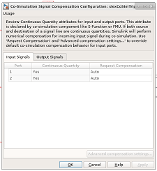
Numerical compensation dialog box

For more information, see Numerical Compensation.

In previous releases, these settings were in separate interfaces and you could only programmatically set the numerical compensation.

Multi-instance Simulink Function blocks

In R2021b, Simulink generated an error when you simulated a Stateflow Chart or MATLAB Function block that called a multi-instance Simulink Function block.

In R2022a, you can simulate a Stateflow Chart or MATLAB Function block that calls a multi-instance Simulink Function block. To specify a multi-instance Simulink Function block, configure the referenced model that includes the Simulink Function block. In the referenced model, set the model configuration parameter Total number of instances allowed per top model to Multiple.

New example of parsing NMEA GPS Text Messages Using Simulink and Python.

A new example shows how to parse text messages in NMEA GPS format using Simulink and Python®. For more information, see Integrate Python GPS Text Message Parsing Algorithms in Simulink.

New example of modeling a distributed wireless tire pressure monitoring system

A new example shows how to design, model, and simulate a distributed monitoring system. In the example, multiple sensors communicate wirelessly with a controller. The controller takes action when it detects a fault condition and maintains a log of fault conditions. The example also shows how to prepare this model to generate code that is deployable on a target hardware platform where the model algorithm is implemented as a component as part of a system.

For more information, see Wireless Tire Pressure Monitoring System with Fault Logging and Prepare Sensor and Controller Models in a Distributed Monitoring System for Code Generation.

 Functionality being removed or changed

SortedOrder parameter no longer supported

Behavior change

Starting in R2019b, the SortedOrder parameter is no longer supported, and its value is ignored.

Bus Editor no longer supports custom import and export functions

Errors

The Bus Editor no longer supports custom import and export functions.

Remove the cm.BusEditorCustomizer.importCallbackFcn and cm.BusEditorCustomizer.exportCallbackFcn registration functions from the sl_customization function. To eliminate both customizations in one operation for a customization manager object named cm, enter:

cm.BusEditorCustomizer.clear
For more information about customizations, see Register Customizations with Simulink.

Project and File Management

Projects: Reduce test runtime in continuous integration workflows using the dependency cache

You can now specify where your project stores the dependency analysis results. In agile development workflows that use Git™ and a continuous integration (CI) server, share the dependency cache file (.graphml) to run an incremental dependency analysis and reduce the test suite runtime. See Continuous Integration Using MATLAB Projects and Jenkins.

To set the project dependency cache file, on the Project tab, in the Environment section, click Details. In Dependency cache file, browse to and specify a GraphML file. If the cache file does not exist, the project creates it for you.

Alternatively, you can create and set the project dependency cache programmatically:

matlab.project.example.timesTable
proj = currentProject;
proj.DependencyCacheFile = "myProjectCacheFile"

Project API: Export top-level and referenced project to previous version using Simulink.exportToVersion

You can now use Simulink.exportToVersion to export the top-level project with all references to open in a previous version of Simulink.

Dependency Analyzer: Save dependency graph as image

You can now save the dependency analysis results as an image. See Export Dependency Analysis Results.

Projects Examples: Determine optimal order for resolving conflicts

When collaborating on a project, a branch merge can lead to several conflicted files. Use the Dependency Analyzer to programmatically determine the optimal order in which to resolve conflicts. See Determine Order for Resolving Conflicts Using Dependency Analyzer.

Text Comparison: Save results as HTML report

You can now use the Comparison Tool to publish text comparison results in an HTML report. For more details, see Compare Text Files.

Folder Comparison: Compare folders in MATLAB Online

Starting in R2022a, you can compare folders and zip files in MATLAB Online.

You can access the comparison tool from:

  • The MATLAB Current Folder browser context menu

  • The Current Project browser context menu

  • The MATLAB Command Window using the visdiff function

 Functionality being removed or changed

Simulink will no longer support getting parameters of the default block diagram

Warns

Getting parameters of the default block diagram will not be supported in a future release. In R2022a, scripts that use get_param(0,parameter) continue to work but throw a warning.

Data Management

Import Simulink Design Verifier sldvData data into Signal Editor user interface

To edit data in MAT-files that contain Simulink Design Verifier™ sldvData structures, use the Simulink.io.SLDVMatFile class to create a custom reader that imports sldvData data into the Signal Editor user interface.

Signal Editor user interface tabular improvements

The Signal Editor user interface has these tabular improvements:

  • You can now navigate through the Signal Editor user interface tabular area using Tab and Shift+Tab. For more information, see Work with Basic Signal Data with a Tabular Editor.

  • To access a context menu of tabular area edits, right-click in the tabular area. You can:

    • Edit a row.

    • Insert or delete a row.

    • Replace the contents of a row with a MATLAB expression.

Root Import Mapper updates

  • When you are ready to map your data to input ports, the Root Inport Mapper now has a context menu that contains the same mapping options as the Map to Model button.

  • The Map to Model options are now enabled by context. In previous releases, all options were enabled and an error message was returned if you selected an unavailable option.

Relax data consistency checking across model hierarchies

Previously, Simulink enforced data consistency across data sources in a model reference hierarchy. Duplicate data definitions could only exist in a hierarchy under these conditions:

  • Each model in the hierarchy can see only one definition.

  • Definitions must be the same across models in the hierarchy.

In R2022a, the model parameter EnforceDataConsistency provides the option to relax the second condition, which allows you to more easily integrate Simulink models for large-scale simulations. When you use the set_param function to set EnforceDataConsistency to off, the current model and the models below it in the model hierarchy can use symbols with the same name but different values as long as each model in the hierarchy can see only one definition of the symbol.

set_param(bdroot,'EnforceDataConsistency','off');

By default, Simulink enforces data consistency, so the parameter is set to on. You cannot set EnforceDataConsistency to on for a model unless each of its referenced models and their variants also set EnforceDataConsistency to on.

Disable consistency checking only when simulating a model in Normal mode. Setting EnforceDataConsistency to off results in error for:

  • Code generation

  • SIL and PIL simulations

  • Simulation of a model hierarchy that contains one or more models running in Accelerator or Rapid Accelerator mode

  • Simulation of a protected model

For more information, see Considerations before Migrating to Data Dictionary.

Model argument enhancements for Simulink.LookupTable and Simulink.Breakpoint objects

In R2022a, these changes enhance the usability of Simulink.LookupTable objects configured as model arguments.

  • When you configure a Simulink.LookupTable object as a model argument, you can now also configure a Simulink.Breakpoint object that is referenced by that Simulink.LookupTable as a model argument. Configure a Simulink.Breakpoint object as a model argument by selecting the Argument check box in the Model Explorer, Simulink.Breakpoint property dialog box, Model Data Editor, or Property Inspector.

    A Simulink.Breakpoint object that is configured as a model argument can be used in a Simulink.LookupTable object when the Breakpoints specification property is set to Reference. When using a Prelookup block with an Interpolation Using Prelookup block in your model, this combination of a Simulink.LookupTable object with a Simulink.Breakpoint object allows you to share a breakpoint object between multiple Prelookup blocks and provide breakpoint values for each model instance.

    When you configure a Simulink.Breakpoint object as a model argument, a parent model can provide the instance-specific value for the model argument by:

    • Using a Simulink.Breakpoint object.

    • Providing an array of numeric values that define the breakpoints. The array must match the design definition for the breakpoint object. Simulink synthesizes a Simulink.Breakpoint object by using the values in the array.

  • When a parent model provides a Simulink.LookupTable object as an instance-specific value for a model argument, Simulink passes only the Table property of the lookup table object to the child model. This action applies to Simulink.LookupTable objects with Specification set to Reference. This behavior change allows you to configure model arguments for Simulink.LookupTable objects and Simulink.Breakpoint objects independently of each other and reuse these objects as instance parameters for multiple Model blocks.

For more information, see Parameterize Instances of a Reusable Referenced Model.

Block Enhancements

C Function block can interface with C++ classes

Starting in R2022a, code that you specify in the C Function block can interface directly with C++ classes defined in your custom code. You can:

  • Instantiate an object of a C++ class defined in your custom code

  • Read and write to public data members of the class object

  • Call public class methods of the object

Previously, it was necessary to write and call C wrapper functions to access C++ classes from the C Function block.

For more information, see Interface with C++ Classes Using C Function Block.

Enhanced Lookup Table Editor

The Lookup Table Editor has a new look and feel.
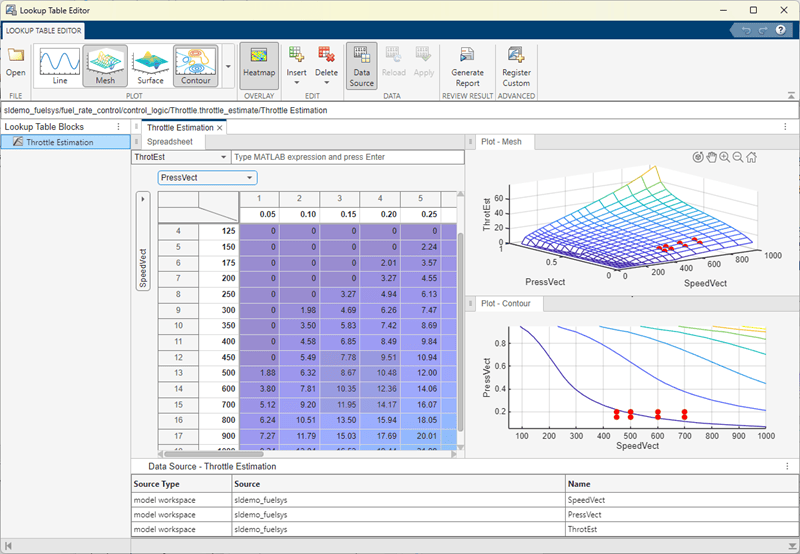
Lookup Table Editor for Throttle Estimation lookup table block in sldemo_fuelsys

This graphic is a view of the Lookup Table Editor for the Throttle Estimation lookup table block in the sldemo_fuelsys model.

Highlights of the new interface include:

  • Multiple ways to access the Lookup Table Editor, including from the Simulink Editor toolstrip, MATLAB command line, and lookup table block dialogs.

  • From within the Lookup Table Editor, the ability to view lookup tables from models loaded in the current MATLAB session.

  • Visualization and editing of lookup table data in a consistent way similar to Microsoft Excel®, regardless of the data source.

  • A navigation field that lets you enter the path to models and subsystems that contain lookup table blocks, and lookup table blocks themselves.

  • Report generation containing lookup table data and surface plots.

    • For 1-D data, the report generates line plots.

    • For more than 1-D data, the report generates surface plots, one plot for each 2-D slice of data.

  • In the tabular area, the Lookup Table Editor contains the same lookup table spreadsheet as is available through the Simulink.LookupTable property dialog box (Edit Lookup Table Data with Lookup Table Spreadsheet).

  • Easy registration of custom lookup table blocks.

  • Generation of different plots for the data, including line, plot, surface, and contour plots.

  • Heatmap views for data.

For more information, see Use the Lookup Table Editor.

Lookup Table blocks updated for better sharing and reuse

These blocks have been updated to better share and reuse utility functions in generated code:

  • n-D Lookup Table

  • 1-D Lookup Table

  • 2-D Lookup Table

  • Interpolation Using Prelookup

Configure Dashboard Scope plots more easily using subplot menu

You can now use the new subplot menu for the Dashboard Scope to:

  • Show or hide data cursors.

  • Zoom out by a fixed amount.

  • Configure the mouse interaction to pan and select or to zoom in time, in y, or in both time and y.

  • Perform a fit-to-view in time, in y, or in both time and y.

To open the subplot menu on the Dashboard Scope block, select the block then click the three dots that appear when you pause on the plot area.
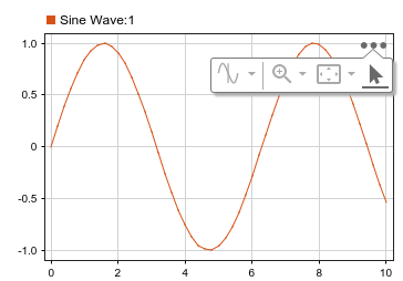
A selected Dashboard Scope block with the subplot menu visible.

In previous releases, you accessed these options using the context menu for the Dashboard Scope block.

New Matrix Operations blocks

The Matrix Operations library has these new blocks:

New Logic and Bit Operations library blocks

The Bit to Integer Converter and Integer to Bit Converter blocks have been added to the Simulink > Logic and Bit Operations library and remain available in the Communications Toolbox > Utility Blocks library. All existing models continue to work.

Trigonometric Function block updates

The Trigonometric Function block now lets you:

  • Change the lookup table algorithm table data types. When you select Lookup for the Approximation method parameter, use the Data Types tab. In previous releases, the table data type was derived from the input data type.

  • Control how the lookup table algorithm interpolates the table value using neighboring breakpoints. Use the new Interpolation method parameter and select Linear point-slope or Flat. In previous releases, Linear point-slope was the only interpolation method.

New Message Triggered Subsystem and Message Polling Subsystem blocks

The Message Triggered Subsystem and Message Polling Subsystem blocks are added to the Messages & Events library for R2022a. Use these blocks to create a subsystem whose execution is controlled by message input. See Message Triggered Subsystem and Using Message Polling and Message Triggered Subsystems.

New Reinitialize Function block and reinitialize ports for Model and Subsystem blocks

The Reinitialize Function block is added to the User-Defined Functions library for R2022a. Use this block to create a subsystem that executes upon a model or subsystem reinitialize event. The block contains an Event Listener block with the Event type set to Reinitialize.

The Model block has a new parameter, Show model reinitialize ports, and the Subsystem block has a new parameter, Show subsystem reinitialize ports. In both cases, when the parameter is selected, the block displays a port or ports that can be used to generate a model or subsystem reinitialize event.

Port-scoped Simulink Function blocks

A new port-scoped visibility option for the Simulink Function block is added for R2022a. To create a port-scoped Simulink Function block, set the Function visibility parameter of the Trigger block inside the Simulink Function block to port and enter the port name in the Scope to port field. Use port-scoped Simulink Function blocks to implement functions called through exporting function ports created by Function Element blocks. See Call Simulink Functions in Other Models Using Function Ports.

New Function Element and Function Element Call blocks

The Function Element and Function Element Call blocks are added to the Ports & Subsystems library for R2022a. Use these blocks to create exporting function ports and invoking function ports, respectively, in referenced models. See Call Simulink Functions in Other Models Using Function Ports.

New capabilities for Parameter Writer block

Starting in R2022a, the Parameter Writer block can write to the following:

  • Parameters of other blocks that are tunable during simulation

  • Instance parameters belonging to a Model block referencing a model

  • Masked subsystem parameters

  • Model workspace variables

Previously, the Parameter Writer block could write only to instance parameters belonging to a Model block referencing a model.

Additionally, starting in R2022a, the Parameter Writer block can be used inside all conditionally executed subsystems, as well as inside Initialize Function, Reinitialize Function, and Reset Function blocks. Previously, the block could be used only inside Initialize Function and Reset Function blocks.

For more information, see Initialize and Reset Parameter Values.

C Function block can access custom code global ND arrays

Starting in R2022a, the C Function block can access global variables defined in your custom code that are multidimensional arrays or struct types with multidimensional array fields.

C Caller and C Function blocks support 64-bit integer types as int64 and uint64

Starting in R2022a, you can import custom C code with 64-bit integer types and use such code with C Caller and C Function blocks, which support these types as int64 and uint64 types in Simulink. Previously, the C Function block did not support 64-bit integer types, and the C Caller block supported such types as fixdt(1,64,0) in Simulink.

C Function block can specify code to initialize conditions when subsystem states reset

Starting in R2022a, you can specify code in a C Function block to execute when enabling a subsystem or model in which the block is placed. Specify this code in the Initialize Conditions Code box in the block dialog. The code executes one time at the start of simulation, and if the block is inside a subsystem or model containing an Enable block with the States when enabling parameter set to reset, the code also executes each time the subsystem or model switches from disabled to enabled. You can use this code to set an initial output value or reset the value of a persistent variable.

Selector and Assignment blocks support out-of-range index checking in accelerator and rapid accelerator modes

Starting in R2022a, the Selector and Assignment blocks can perform run-time checking of index values to ensure that they are not out of range when simulating a model in accelerator or rapid accelerator mode. Previously, these blocks performed such run-time checking only when simulating in normal mode, and an out-of-range index in accelerator or rapid accelerator mode could produce unpredictable results or cause MATLAB to crash. See Check for out-of-range index in accelerated simulation (Assignment) and Check for out-of-range index in accelerated simulation (Selector).

For Each Subsystem block accepts variable-size signals

Starting in R2022a, you can use the For Each Subsystem block with one-dimensional variable-size signals, including variable-size arrays of buses. See Limitations of For-Each Subsystems.

Specify origin for value bar and needle on customizable dashboard blocks

You can specify an origin on the scale for several blocks in the Customizable Blocks library:

The origin specifies the value on the scale from which the needle moves and the value bar grows. For example, the origin for this gauge with a scale range from –100 to 100 is set to 0, such that the value bar indicates the value of the connected signal relative to zero.

Custom Gauge block with Origin value of 0

By default, the origin is specified as auto, and the value for the origin is the minimum value for the scale.

Resize and reposition foreground image for customizable dashboard blocks

The blocks in the Customizable Blocks library have an option to add a foreground image as part of the design for a block. Starting in R2022a, you can rotate, resize, and reposition the foreground image within the block design.

For example, if the foreground image has the wrong orientation when you add it to the block, click the rotation button to rotate the image to the correct orientation in 90 degree increments.
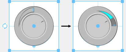
Custom radio knob with the foreground in its default orientation (left), and with the foreground rotated ninety degrees (right)

Change scale direction for customizable dashboard blocks

Several dashboard blocks in the Customizable Blocks library allow you to specify the direction for the scale:

Lamp block in Customizable Blocks library supports specifying state values as ranges

The Lamp block connects to a signal and displays a color that reflects the value of the connected signal. In previous releases, you could only specify a discrete value for each state and design a Lamp block that indicated when the connected signal had that specific value. Starting in R2022a, you can specify each state value as a range and design a Lamp block that indicates when value of the connected signal is within each range.

View and edit each state for customizable Lamp block in design mode

Starting in R2022a, you can view and edit each state for the customizable Lamp block in design mode, and you can modify more aspects of the block appearance for each state. For example, you can now design a lamp that uses a different icon for each state.
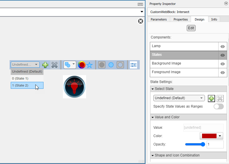
Customizable Lamp block in design mode with the Design tab of the Property Inspector visible.

Change opacity of state colors for customizable Lamp block

For the customizable Lamp block, you can now change the opacity of the color that you set for a state.

From Spreadsheet block Range Selection tool updates

Range Selection from the Range parameter of the From Spreadsheet block has these changes:

  • The interface has an updated toolstrip in the top right. There is no longer a Help icon for this interface. Instead, see the Range parameter documentation.

  • The Range field is now Selection/History.

  • If you do not specify a range in the Range parameter, Range Selection now displays all cell entries as selected.

Unit Conversion block now accepts multidimensional signals

The Unit Conversion block now accepts multidimensional signals at the block input port.

Simulink.ImageType data type for image signals

In R2022a, you can now use the Computer Vision Toolbox™ to specify an image of the Simulink.ImageType (Computer Vision Toolbox) data type and simulate the model. Specify this data type for signals and other data in the model. The Simulink.ImageType data type is an encapsulated object that defines an image by using fixed meta-attributes specific to this data type.

The blocks listed in this table support simulation and code generation of a Simulink.ImageType object.

Block LibraryBlock Name
Sources
  • Ground

  • Inport

  • Outport

Signal Routing
  • Goto

  • From

  • Data Store Read

  • Data Store Write

  • Data Store Memory

  • Switch

  • Multiport Switch

  • Merge

  • Variant Source

  • Variant Merge (internal block added during code generation)

  • Mux

  • Demux

  • Vector Concatenate, Matrix Concatenate

  • Selector

Sink
  • Terminator

  • To Workspace (simulation only)

  • Record (simulation only)

Ports & Subsystems
  • Subsystem, Atomic Subsystem, CodeReuse Subsystem

  • Enabled Subsystem

  • Triggered Subsystem

  • Function-Call Subsystem

  • If

  • Switch Case

  • Resettable Subsystem

  • For Iterator Subsystem

  • Model

Discrete
  • Unit Delay

Signal Attributes
  • Signal Conversion

  • Signal Specification

User-Defined Functions
  • Initialize Function, Reset Function, and Terminate Function

  • Simulink Function block with side I/O and arguments

For more information, see the Computer Vision with Simulink: Specify image data type in Simulink model (Computer Vision Toolbox) release note.

Discrete PID Controller Blocks: Improve execution time of generated code

By default, the Discrete PID Controller and Discrete PID Controller (2DOF) blocks take the integral gain as input and multiply it by the sample time internally as a part of performing the integration. You can now configure the blocks to accept the integral gain premultiplied with the sample time as an input. Doing so improves the execution time of the generated code. Therefore, when you have limited processing power, enable the Use I*Ts parameter and specify the Integral parameter value as the integral gain multiplied by the controller sample time.
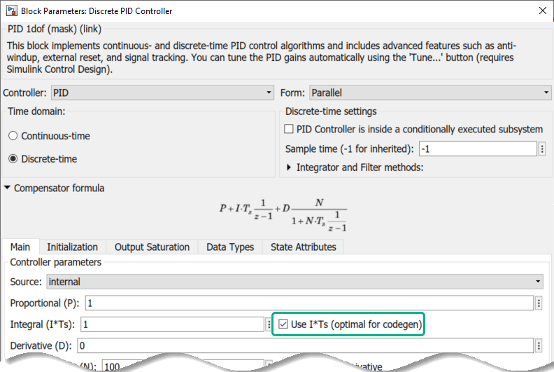
Discrete PID Controller block parameters.

Additionally, if your controller uses an anti-windup mechanism, enhancements to the clamping method also reduce the execution time of the generated code.

 Functionality being removed or changed

To Workspace block logging enhancements

Behavior change

Starting in R2022a, the To Workspace block supports:

  • Logging an array of buses.

  • Logging signals with string and half data types.

  • Logging int64 and uint64 data using built-in data types.

  • Using the Timeseries format in rapid accelerator simulations.

  • Using the Timeseries format for To Workspace blocks inside For-Each subsystems.

Data logged using To Workspace blocks also streams to the Simulation Data Inspector during simulation.

 Compatibility Considerations
  • In prior releases, the To Workspace block logged int64 and uint64 as a fi object when a license for Fixed-Point Designer™ was available and as double data when the license was not available. Starting in R2022a, the To Workspace block always logs int64 and uint64 data using the built-in data types.

  • In prior releases, data logged using the To Workspace block only logged to the workspace and was overwritten for each simulation unless you changed the logging variable names or saved the results yourself.

    Starting in R2022a, data logged using To Workspace blocks logs to the Simulation Data Inspector as well as the workspace. When you run multiple simulations in a single MATLAB session, the Simulation Data Inspector automatically retains results from each simulation so you can analyze the results together. Starting in R2022a, because data logged using To Workspace blocks streams to the Simulation Data Inspector, this data is also retained.

    Logging large amounts of data or running many simulations can produce large amounts of data that fill up disk space. To learn how to control the amount of data retained in the Simulation Data Inspector, see Limit the Size of Logged Data.

Access to Simulink Scope through Handle Graphics API will be removed

Still runs

The underlying graphics of the Simulink Scope block will change in a future release. Once that happens, you will not be able to access or modify the Simulink Scope block through the handle graphics API.

Update any undocumented use of handle graphics APIs that access the Scope window.

Floating Signal Selection will be removed

Still runs

The floating signal selection feature (Lock button used to enable the selection of multiple signals) in the Floating Scope block will be removed in a future release. To connect signals to your floating scope, use the existing signal selector (signal selector icon on floating scope) instead. For more details, see Add Floating Scope Block to Model and Connect Signals.

Ability to dock Scopes to MATLAB desktop will be removed

Still runs

The ability to dock the Simulink Scope, Time Scope (DSP System Toolbox), Floating Scope and Scope Viewer to the MATLAB desktop will be removed in a future release.

SampleInput parameter will be removed

Still runs

The SampleInput parameter of the Simulink Scope, Time Scope (DSP System Toolbox), Floating Scope and Scope Viewer (currently accessed through the command line API) will be removed in a future release.

Connection to Hardware

Support added for 64-bit Android applications

Use the Simulink Support Package for Android® Devices to build and deploy Android applications on your device that supports 64-bit Android application packages (APK). You can use the Android Device (64-bit) option under Hardware board in the Configuration Parameters dialog box to generate a 64-bit APK for your Android application. Alternatively, you can use the Create 64 bit library as well option under Android Device hardware board to generate a 32-bit and a 64-bit APK for your Android application.

Support added to integrate algorithm to existing Android application

Use the Simulink Support Package for Android Devices to integrate an algorithm developed in Simulink into an existing Android application using Android Studio. Use the Create Android library module for Simulink model option in the Configuration Parameters dialog box to create a library module for the Simulink model that can be further integrated with the code of an existing Android application. This option is available under App options in the Configuration Parameters dialog box for both Android Device and Android Device (64 bit) hardware options.

Better visual display and auto rotate applications on Android devices

Starting R2022a, you can now navigate easily through the tabs of an application deployed on your Android device. If your model contains a Camera or Scope block from Simulink Support Package for Android Devices and is deployed on your Android device, you can automatically rotate the application with the Android device. Previously, you could not automatically rotate the application.

Support added for Arduino compatible ESP32-WROOM boards

The Simulink Support Package for Arduino® Hardware now supports deploying Simulink models on the ESP32-WROOM boards. The ESP32-WROOM (Arduino Compatible) option has been added to the Hardware board drop-down list in the Configuration Parameters dialog box. Starting R2022b, you can use these ESP32-WROOM boards:

  • ESP32-WROOM-DevKitV1(30 pin)

  • ESP32-WROOM-DevKitV1(36 pin)

  • ESP32-WROOM-DevKitC(38 pin)

The support package also provides real-time execution profiling for the Simulink models deployed on the ESP32-WROOM boards. You can use these blocks from the support package library with the ESP32-WROOM boards.

Digital InputProtocol EncoderBNO055 IMU SensorLSM6DS0 IMU Sensor
Digital OutputProtocol DecoderTachometerLSM6DSR IMU Sensor
Analog InputExternal InterruptAPDS9960 SensorLSM303C IMU Sensor
Analog OutputWiFi TCP/IP ReceiveMPU9250 IMU SensorLPS22HB IMU Sensor
PWMWiFi TCP/IP SendMPU6050 IMU SensorHTS221 Humidity Sensor
Serial ReceiveWiFi UDP ReceiveLSM9DS1 IMU SensorEncoder
Serial TransmitWiFi UDP SendLSM6DS3 IMU SensorADXL34x Accelerometer
I2C WriteWiFi ThingSpeak ReadLSM6DS3H IMU SensorCCS811 Air Quality Sensor
I2C ReadWiFi ThingSpeak WriteLSM6DSL IMU SensorICM20948 IMU Sensor
SPI Write ReadUltrasonic SensorLSM6DSM IMU SensorVL530x Time of Flight Sensor

Hardware support extended for real-time execution of generated code on Arduino boards

The Simulink Support Package for Arduino Hardware now provides real-time execution profiling for the Simulink models deployed on these Arduino boards:

  • Arduino Uno

  • Arduino Mega ADK

  • Arduino Mega 2560

  • Arduino Leonardo

Previously, real-time execution profiling was supported only on ARM® architecture-based Arduino boards.

Select serial communication port for external and PIL modes on Arduino boards

For Simulink Support Package for Arduino Hardware, you can now select any serial communication port on your Arduino board to run the models in either external (Monitor & Tune) or PIL modes. Previously, you could select only serial port 0 on your Arduino board.

Support extended for executing multitasking models for Arduino Nano 33 BLE Sense board

Prior to R2022a, using the Simulink Support Package for Arduino Hardware for executing and deploying multitasking models on Arduino Nano 33 BLE Sense board was not supported.

Starting in R2022a, you can deploy models containing blocks running at different sample rates on your Arduino Nano 33 BLE Sense boards.

Control pan and tilt motions using PCA9685-based PWM driver

With the addition of the Pan Tilt Hat block to the Raspberry Pi® Blockset, you can now control the pan and tilt motions of the pan-tilt hardware using the PCA9685 kernel module.

Adjust and set video and camera parameters using V4L2 Video Capture block in Raspberry Pi

Using the V4L2 Video Capture block from Raspberry Pi Blockset, you can now adjust various parameters for an input video such as brightness, saturation, contrast, sharpness, and flip along vertical and horizontal axes. You can also adjust various parameters of your camera such as pan and tilt angles, zoom-in and zoom-out, and enable manual focus using the block.

Improved build and deployment speeds for Raspberry Pi Blockset

Before R2022a, in the Raspberry Pi Blockset, the generated code and the driver source code were compiled sequentially. From R2022a, the code is compiled in parallel, thus reducing the time taken to build models. You can change this default behavior and choose to build the model sequentially by clearing the Enable parallel build parameter under Build options in the Configuration Parameters dialog box.

Manually set XCP-based polling time for Simulink model running on Raspberry Pi

You can now manually set the XCP-based polling time for Simulink models that contain blocks from the Raspberry Pi Blockset running in the external mode (Monitor & Tune). A new parameter, Set XCP target polling time, has been added in the Configuration Parameters dialog box. Previously, the polling time for Simulink models running in external mode was calculated automatically.

Higher data acquisition rates using Connected I/O with Arduino boards

The Simulink Support Package for Arduino Hardware now supports higher data acquisition rates for sensor/peripheral blocks with Arduino boards using Connected I/O. In the Connected I/O mode, use the sensor/peripheral blocks in the model, enable Simulation Pacing, and then set the Simulation time per wall clock second to 1 for a higher data acquisition rate.

Read distance to target object using VL53L0X sensor

The Simulink Support Package for Arduino Hardware now supports interfacing the VL53L0X sensor with Arduino hardware. You can use the new VL503L0X Time Of Flight Sensor block to measure the distance to a target object for a complete field of view. The block also provides the option to select one of four ranging modes based on your requirements.

Read linear acceleration, angular velocity, magnetic field, and temperature using ICM-20948 sensor

The Simulink Support Package for Arduino Hardware now supports interfacing the ICM-20948 nine-axis sensor with Arduino hardware. You can use the new ICM20948 IMU Sensor block to measure linear acceleration, angular velocity, and magnetic field along the X, Y and Z-axes, and to measure temperature. The block also provides the option to generate the data ready interrupt.

Read eCO2 and eTVOC using CCS811 sensor

The Simulink Support Package for Arduino Hardware now supports interfacing the CCS811 sensor with Arduino hardware. You can use the new CCS811 Air Quality Sensor block to measure the equivalent CO2 (eCO2) and the equivalent total volatile organic compound concentration (eTVOC) for indoor air quality monitoring. The block also provides the option to use temperature and humidity data to enable compensation (either by specifying the humidity and temperature values or by interfacing CCS811 with an external sensor).

Read linear acceleration using ADXL34x family of accelerometers

The Simulink Support Package for Arduino Hardware now supports interfacing the ADXL34x family of accelerometers (ADXL343, ADXL344, ADXL345, and ADXL346) with Arduino hardware. You can use the new ADXL34x Accelerometer block to measure linear acceleration along the X, Y and Z-axes. The block also provides the option to enable the data ready interrupt.

MATLAB Function Blocks

Cell Array Type for Non-Tunable Parameters

In MATLAB Function blocks, you can use cell arrays as non-tunable parameter data. To use cell-arrays as non-tunable parameters in your MATLAB Function block, see Configure MATLAB Function Block Parameter Variables and ensure that the Tunable option is cleared.

 Variable Size property applies only to output variables

Starting in R2022a, the Variable size property only applies to MATLAB Function block variables with the Scope property set to Output. Input variables now inherit size variability from their corresponding signals. Prior to R2022a, this property could also be applied to MATLAB Function block variables with Scope set to Input. Updating a model created in a previous release disables this property for input variables.

You can still specify the property for variables used in both the input and output of the function declaration statement. For example, if you define the function y = myFunction(y), the variable y has this property.

Symbols pane replaces Ports and Data Manager

In R2022a, the Ports and Data Manager has been removed. To manage variables, function call outputs, and input triggers in MATLAB Function blocks, use the Symbols pane and the Property Inspector.
This image shows the Symbols pane as it appears in a new MATLAB Function block.

For more information on managing variables, function call outputs, and input triggers with the Symbols pane and Property Inspector, see Create and Define MATLAB Function Block Variables, Manage Function Call Outputs of a MATLAB Function Block, and Manage the Input Trigger of a MATLAB Function Block.

New Code Generation Readiness Tool: View more information and navigate through readiness results more easily

In R2022a, the Code Generation Readiness Tool has a new user interface, more information, additional functionality, and improved navigation. In addition, you can now use the Code Generation Readiness Tool in MATLAB Online™.
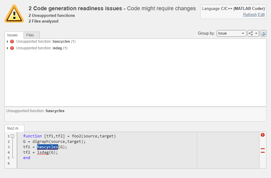
Screenshot of the code generation readiness tool with sample code and analysis results.

In addition to the existing functionalities, you can now:

  • View your MATLAB code inside the Code Generation Readiness Tool. When you select an issue, the part of your MATLAB code that caused this issue gets highlighted.

  • Group the readiness results either by issue or by file.

  • Select the language that the code generation readiness analysis uses.

  • Refresh the code generation readiness analysis if you updated your MATLAB code.

See Check Code Using the Code Generation Readiness Tool and coder.screener.

coder.ScreenerInfo object: Access code generation readiness information programmatically

In R2022a, you can export the code generation readiness information about your MATLAB code to a variable in your base workspace. This variable contains a coder.ScreenerInfo object whose properties contain information about:

  • MATLAB files analyzed by the Code Generation Readiness Tool

  • Code generation readiness messages

  • Calls to functions not supported for code generation

To export code generation readiness information about your the files foo1.m, foo2.m, and foo3.mlx to the variable info in your base workspace, execute this function call:

info = coder.screener('foo1.m','foo2.m','foo3.mlx')

You can also export the entire report to a MATLAB string by executing the object function textReport:

reportString = textReport(info)

See:

Code generation for more toolbox functions

In R2022a, you can generate code for many additional toolbox functions and objects. For a list of all functions and objects that are supported for code generation, see:

Modeling Guidelines

 High-Integrity Systems Modeling Checks: Improve quality and compliance with guidelines ​​​​

In R2022a, you can use these high-integrity modeling guidelines:

High-Integrity GuidelineEquivalent Model Advisor Check
hisl_0075: Usage of library linksCheck for disabled and parameterized library links
hisl_0101: Avoid operations that result in dead logic to improve code complianceCheck for unreachable and dead code

 Compatibility Considerations

These guidelines were removed in R2022a:

High-Integrity GuidelineCorresponding Modeling Check

hisf_0003: Usage of bitwise operations

Use hisl_0019: Usage of bitwise operations.

Check usage of bitwise operations in Stateflow charts.
hisf_0009: Strong data typing (Simulink and Stateflow boundary)Check for Strong Data Typing with Simulink I/O

S-Functions

Programmatically configure S-functions using the S-Function Builder block

Starting in R2022a, you can use functions to configure an S-Function Builder block to build an S-function for your model. You can use the functions to:

  • Configure settings, including build options and options to support model coverage and design verification.

  • Specify user code for the S-function methods.

  • Compile the S-function source and MEX.

For more information, see Implement C/C++ Code Using S-Function Builder.

 Functionality being removed or changed

Level-1 Fortran S-function will be removed in a future release

Still runs

Level-1 Fortran S-functions will be removed in a future release. Use Level-2 Fortran S-functions instead. To learn more about Level-2 Fortran S-functions, see Create Level-2 Fortran S-Functions and explore the sfcndemo_atmos example.