R2023b

New Features, Bug Fixes, Compatibility Considerations

New Model Finder user interface: Index, search, filter, and browse Simulink models in multiple databases

Model Finder has a new user interface (UI) to index, search, filter, and browse Simulink® examples, models, and projects across multiple databases. Using multiple databases enables you to create separate indexes for similar set of models for easier maintenance.

To open the Model Finder UI, type modelfinderui in the MATLAB® Command Window. The Model Finder UI has these sections:

  1. Search box — Text box to enter the search terms to find models.

  2. Configure Databases — Menu of the available databases to search. You can select a single database or multiple databases from the list to set the search location.

  3. Search Summary — Display of the examples, models, and projects matching the search query. For each match, the Model Finder UI displays a summary with the name of the example, model, or project; the matched search terms highlighted in yellow; names of MathWorks® products, location of the model; and a button to open the example, model, or project.

  4. Recent — List of up to five recent examples, models, or projects you opened using the Model Finder UI.

  5. Filters — Filters to narrow down search results in response to your search query. The Model Finder UI displays the following filters:

    • Matched In — Locations of the text that matches the search terms. This includes the model description, annotation, or block.

    • Product — Names of the MathWorks products used by the examples, models, or projects.

    • Location — Paths to the Simulink models or projects.

    • Example Component — Names of the example components.

  6. Info Panel — Description of the example, model, or project, and the block count of the selected search result.

For more information on the Model Finder UI, see Model Finder.

To configure database settings, use these functions:

For more information on Model Finder, see Index and Search Models with Model Finder.
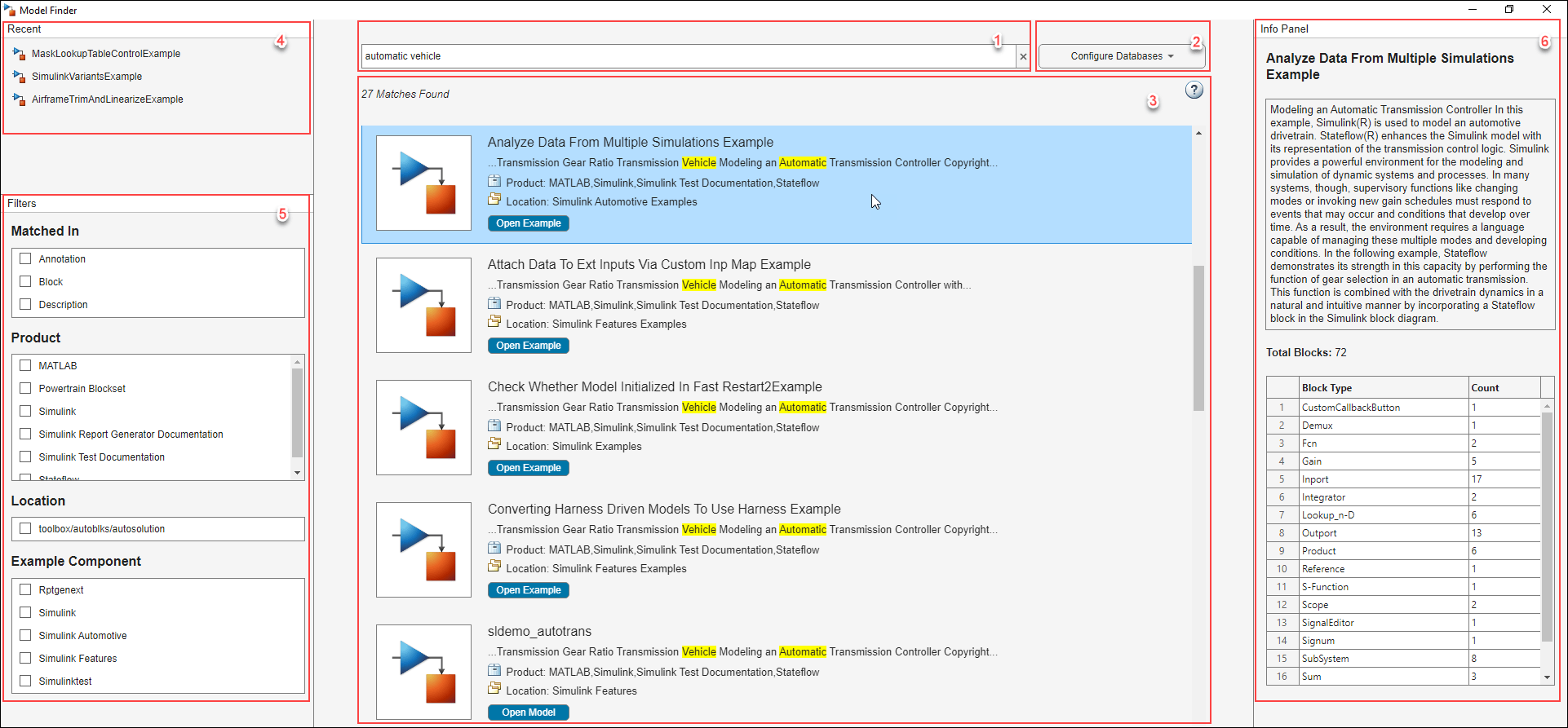
View of the Model Finder UI. Left side displays the recent search history and filters. In the middle, the search bar and search results are seen. The right side displays the info panel with the description and count of blocks of the selected search result.

New Connectors button to display different connections between blocks

Starting in R2023b, the Debug tab has a new Connectors button. This new Connectors button replaces the existing Function Connectors and Schedule Connectors buttons. This button also allows you to access all the connector options.

  • Three new connectors: State Connectors, Parameter Connectors and Data Store Connectors.

  • Two existing connector options: Function Connectors and Schedule Connectors.

Connector is a debug tool that displays the connection between different blocks in a Simulink model. To visually display the list of connectors, on the Debug tab, select Information Overlays > Connectors. The Connectors pane opens on the right side of the Simulink Editor. Select the required connector options to display the corresponding connectors. The arrow heads of the connector lines indicate the direction of signal flow.

This example shows a model with four connector options selected.
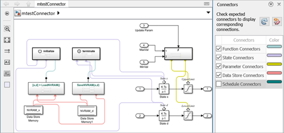
Model with four connector options selected

Create Model block ports without entering referenced model

Starting in R2023b, you can create ports on Model blocks without entering the referenced model the same way you can on a Subsystem block.

To create a port, pause on any of the four edges of the Model block. When your pointer turns into a cross, click. A new port appears on the edge you clicked, highlighted in blue.
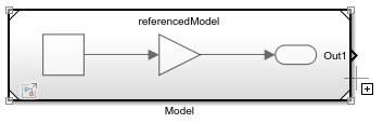
The pointer is a cross and is paused on the right edge of a Model block.

Pause your pointer on the new port. In the action menu that expands, select the type of port you want to create.
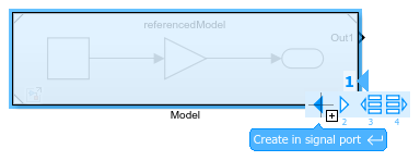
Action menu for port creation with the pointer paused on the Create in signal port button

Alternatively, to create a port, drag a signal line from the model element you want to connect to the edge of the Model block. Dragging from a port block creates a new port of the same type. For example, dragging from an Inport block creates a new input port. Dragging from a Subsystem or Model block port that represents a port block also creates a new port of the same type as the port block.

To delete an existing port, select the port and press Delete. To delete multiple ports, press Shift and select the ports. Then, press Delete.

For more information about creating Model block ports, see Add Ports to Model Reference Interface.

You can use the same approach to add ports to and delete ports from System Composer™ Reference Component (System Composer) blocks and AUTOSAR Blockset Component blocks that are linked to models.

Diagnostic Viewer: Faster reporting of diagnostic messages

Reporting of diagnostic messages when you load, simulate, or build a model shows improved performance.

For example, if you report 100,000 diagnostic messages on the Diagnostic Viewer, performance in R2023b is about 1.7x faster than in R2023a.

The approximate timings to report 100,000 warning messages for the model vdp using the function sldiagviewer.reportWarning in R2023b and R2023a are:

R2023b: 60.5 s

R2023a: 104.4 s

The reporting was timed on an Intel® Xeon® W-2133 CPU E5-1650 v4 @ 3.60GHz test system.

Share your feedback to analyze and improve the diagnostic messages

Give us your feedback for the diagnostic messages displayed in the Diagnostic Viewer when you simulate or build a model. Feedback will be used to improve the diagnostic message.

Click the Add Comment button Provide Feedback button next to the diagnostic message in the Diagnostic Viewer and enter your feedback in the text box. The character limit of the feedback is 1024 characters. To request help or report a technical bug, contact Technical Support at Contact Support.
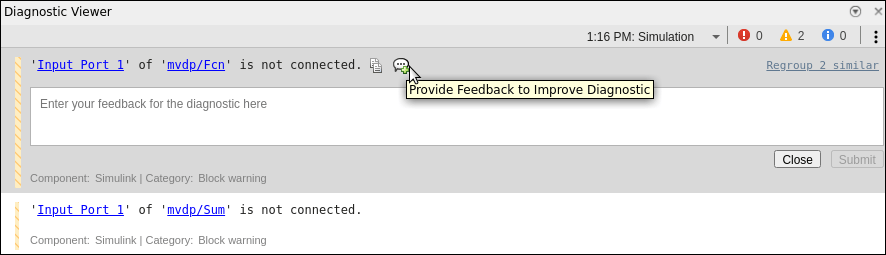
View of the Diagnostic Viewer with the text box to provide feedback.

Reload specific Simulink Toolstrip component using slUpdateToolstripComponent function

You can customize the Simulink Toolstrip by adding tabs that focus on specific workflows. When you create custom toolstrip components, you create a resources folder containing JSON files that specify component properties and, optionally, icon image files. You can edit the custom components by editing these files. To see the resulting changes in the toolstrip, you must reload the component.

Starting in R2023b, to see the changes in the toolstrip, instead of reloading the entire toolstrip using the slReloadToolstripConfig function, you can reload a specific component using the slUpdateToolstripComponent function. For the function input, specify the component name or the path to the parent folder of the resource folder.

For example, open Simulink and create a new custom toolstrip tab by entering these commands in the MATLAB Command Window.

Note

The first command places the current folder on the MATLAB path. For more information, see slCreateToolstripComponent.

slCreateToolstripComponent("componentName");
slCreateToolstripTab("propertiesFileName","componentName",Title="CUSTOM TAB");

A resources folder is created in the current folder. To change the tab title, open the resources folder and then the json folder. Open the propertiesFileName.json file and change "title": "CUSTOM TAB" to "title": "NEW". Save the file.

To reload the component, enter this command.

slUpdateToolstripComponent("componentName")

In the toolstrip, the title of the custom tab changes to New.

For more information about custom Toolstrip components, see Create Custom Simulink Toolstrip Tabs.

Open example models from the documentation or command line

Use openExample to open example models from the command line. For example, to open the f14 model, enter:

openExample('f14')
You can also access the example models from the documentation, including the examples listed in this table.

 Functionality being removed or changed

New keyboard shortcut for opening and hiding Property Inspector on macOS

Behavior change

Starting in R2023b, on macOS, the keyboard shortcut to open or hide the Property Inspector is command+option+O.

For more information about Simulink keyboard shortcuts, see Keyboard Shortcuts and Mouse Actions for Simulink Modeling.

Simulation Analysis and Performance

New Timing Legend with enhanced visualization and organization

The redesigned Timing Legend has visualization and organization that simplifies the analysis of timing information needed for the execution of the blocks in your Simulink model.

Starting in R2023b, you do not need to update the diagram for your model when changing the sample time visualization options or when launching the Timing Legend after model compilation.

Visualization in the Timing Legend is now more organized. Same-rate specifications are displayed as one row that you can expand for details. When using the Coloring, only the borders of the block display the color of the sample time rate. Check boxes for sample times also allow you to choose specific sample times to display. The Timing Legend now also displays base rate and scalar multipliers for analysis of the discrete time-lines.

Changes from the previous versions of the Timing Legend include:

  • The origin highlighting menu at the top of the Timing Legend is replaced by block path links. The block path links are available when you expand a sample time row.

  • All discrete sample times (for example, periodic partitions, discrete export function etc.) with the same sample time specification are now combined into the same row.

  • Triggered sample time rates are now visualized as their source sample times since it illustrates the sample rate that is driving the trigger.

  • Annotations for aperiodic partition, reset, initialize, reinitialize, and terminate sample times no longer use their event names as annotations. These sample times have their own concise annotations.

  • The colors used in the Timing Legend have been changed and reduced in number which provide more contrast to improve accessibility and usability.
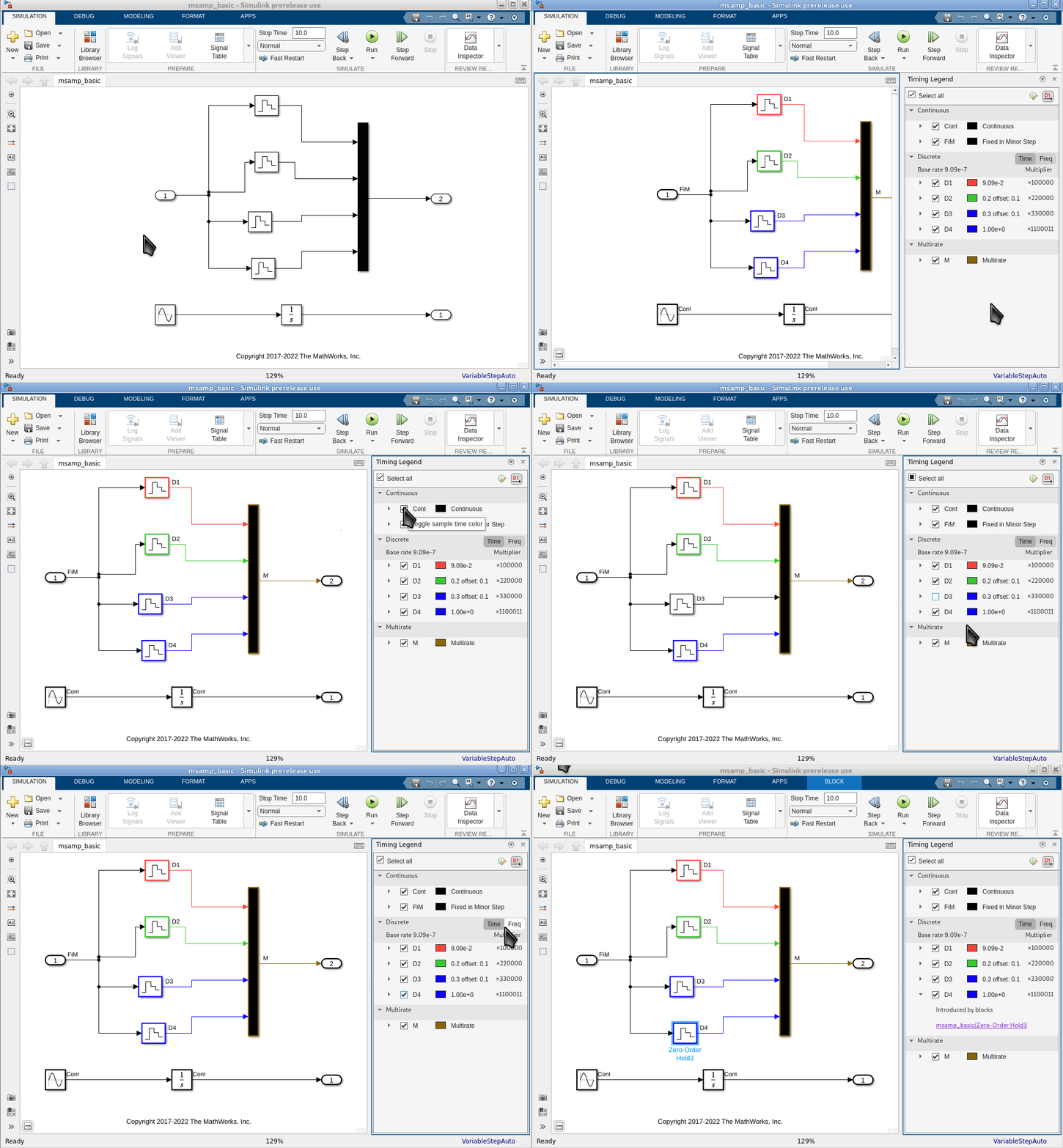
The image is a gif that shows that the sample time rows can be expanded. It also shows the new colors of the Timing Legend, and how these new colors are used to color only the borders of the block.

Specify a block to execute first or last in the execution order

Starting in R2023b, you can designate a Simulink block to execute first or last when the block is inside a nonvirtual subsystem or at the root level of a model. A subset of Simulink blocks support this new setting for the Execution Order property.

To configure a block to execute first or last, in the Block Parameters dialog box, from the Execution Order list, select First or Last. You must update the model (Ctrl+D) for this configuration to take effect.
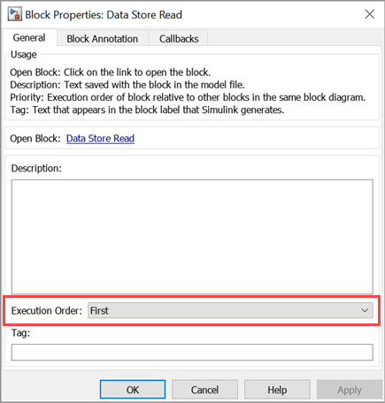
Execution Order configuration for Data Store Read block

This example shows the execution order of blocks at the root level of a model. The Execution Order property of the Data Store Read block and the Data Store Write block is set to First and Last, respectively. For more information, see Specify Block Execution Order, Execution Priority and Tag.
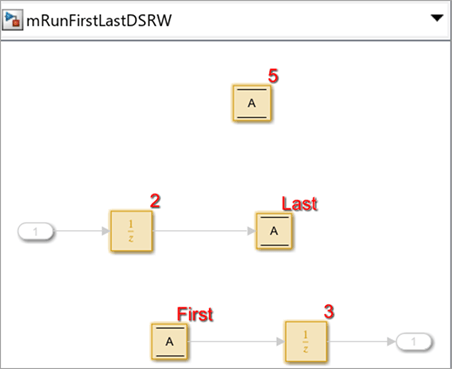
Model that represents execution order First or Last

By default, the Execution Order property of a block is set to Based on priority.

Support for unbounded variable-size signals in Simulink

Starting in R2023b, you can use unbounded variable-size signals to transmit data with unbounded size between components in a model. To specify variable-size signals as unbounded, set the signal size to Inf.

A subset of Simulink blocks and features support unbounded variable-size signals. These are a few different use cases.

  • Output unbounded variable-size signals from the Inport block.

  • Output unbounded variable-size arrays from the MATLAB Function block.

  • Specify buses containing data with unbounded size using a Simulink.BusElement object.

  • Specify signals containing data with unbounded size using a Simulink.Signal object.

For example, you need to configure the MATLAB Function block to output an unbounded variable-size array of size ([Inf 6]). To configure this block, in the Simulink Editor, on the Modeling tab, from Design gallery, select Model Explorer. In the Model Explorer window, select the MATLAB Function. Specify theSize as [Inf 6] and select the Variable size property.
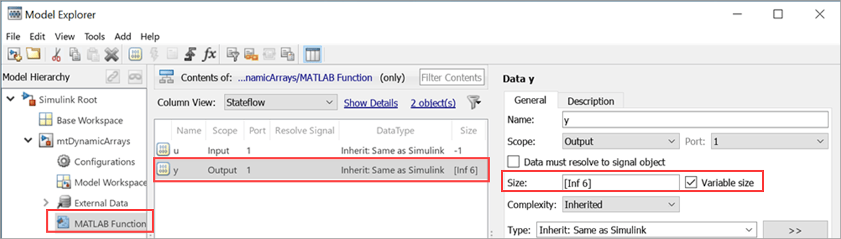
Set up MATLAB Function block to output unbounded variable-size array

This example shows four use cases when the Simulink blocks and objects are configured to use unbounded variable-size signals.
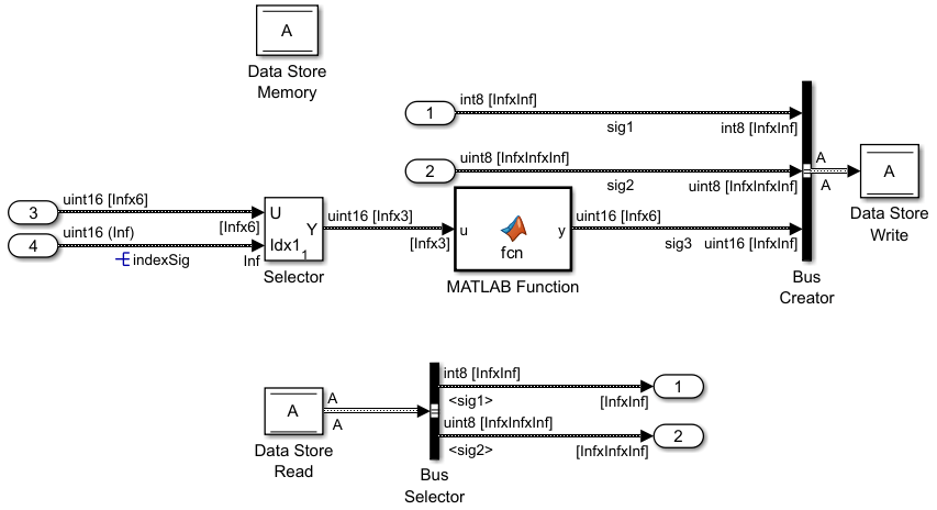
Model that uses unbounded variable-size signals

Nonvirtual mathematical operation blocks, including but not limited to the Gain block, Add block, Product, Matrix Multiply block, Math Function block, and Trigonometric Function block, do not support unbounded variable-size signals. To implement these math operations for unbounded variable-size signals, use the MATLAB Function block or S-Function block. For more information, see Unbounded Variable-Size Signals.

Keyboard shortcuts for Step Over, Step In, and Step Out debugging controls in Simulink Toolstrip

In R2023a, the Step Over, Step In, and Step Out buttons in the Simulink Toolstrip added the ability to advance a simulation block by block while paused within a time step. Starting in R2023b, you can use keyboard shortcuts to control these actions. The keyboard shortcuts for the buttons in the Simulink Editor are the same as the keyboard shortcuts for these buttons in the Stateflow® Editor and the MATLAB Function Block Editor.

TaskShortcut
Step over

F10

On macOS, press Shift+Command+O.

Step in

F11

On macOS, press Shift+Command+I.

Step out

Shift+F11

On macOS, press Shift+Command+U.

Initialization time in simulation metadata includes time to set up simulation using Simulink.SimulationInput object

The timing information captured in the simulation metadata for simulations configured using Simulink.SimulationInput objects more closely matches the result of timing the call to the sim function using tic and toc. The initialization time now includes the time spent setting up the simulation based on the Simulink.SimulationInput object, such as:

  • Time to build model references, including time to set up workers for parallel builds

  • Time to run the presimulation callback function specified using the setPreSimFcn function

  • Time to set variable, block parameter, and model parameter values

The simulation metadata is returned as part of the Simulink.SimulationOutput object that contains all the simulation results. To view the timing information for a simulation, get the Simulink.SimulationMetadata object from the Simulink.SimulationOutput object and view the TimingInfo property of the Simulink.SimulationMetadata object.

out = sim(simIn);
simMeta = out.SimulationMetadata;
simTiming = simMeta.TimingInfo

Inf values supported for initial states data

When you specify an initial state for your model using the Initial state parameter, the data you specify can now contain Inf values, including when you specify the initial state as a Simulink.op.ModelOperatingPoint object. For example, you could load an initial state for the model with one or more Inf values in a test of the system response to invalid state values. In previous releases, the software issued an error when the initial state data contained Inf values.

Usability enhancements for viewing streaming data and text in the Simulation Data Inspector

In R2020b, the Freeze display button was added to the Simulation Data Inspector. In R2023b, this button has been and enhanced and renamed Hold .

  • Previously, when streaming signals to the Simulation Data Inspector, you could freeze the display to prevent the plots from wrapping or scrolling as new data came in. However, signals continued to plot until hitting the right edge of the plotting area.

    Now, the Simulation Data Inspector stops plotting data immediately when you hold the display. For more information about how to hold the display of streaming data, see View Streaming Data in the Simulation Data Inspector.

  • Previously, the Freeze display icon appeared only when streaming data.

    Now, the Hold button is always visible. When a simulation stops, the button becomes inactive.

The text editor now has a subplot menu and context menu like all other visualizations. You can click the three dots in the upper right corner of the text editor or right-click anywhere on the subplot to change the visualization, clear the subplot, maximise the subplot, or take a snapshot.
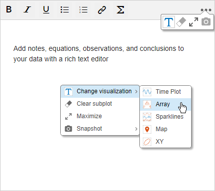
Add notes, equations, observations, and conclusions to your data with a rich text editor. In the upper right corner, the subplot menu is expanded to show the options to change the visualizations, clear the subplot, maximise the subplot, or take a snapshot. In the center of the text editor, the context menu shows the same menu choices with the Change visualization option expanded.

Import ROS Bag files into the Simulation Data Inspector

You can import data from ROS Bag files into the Simulation Data Inspector to view and analyze the ROS data on its own or alongside other simulation data and imported data. Importing bag files into the Simulation Data Inspector requires a ROS Toolbox license.

Configure Simulation Data Inspector plots using new functions

Three new functions have been added to help you programmatically configure the legend position and subplot layout in the Simulation Data Inspector.

Performance and visualization improvements for the XY plot

Performance has been improved for the XY visualization in the Simulation Data Inspector and the Record, XY Graph block, making XY visualizations more responsive.

Changes have also been made to the default appearance of XY visualizations. Previously, by default, data on an XY plot appeared as lines with no markers. Now, data is shown as a scatter plot. You can modify the appearance of the XY plot by clicking Visualization Settings . Select or clear Line and Markers to display only markers, only lines, or both markers and connecting lines. When you save a Simulation Data Inspector session, that session file also saves your line and marker style preferences.

Log unbounded variable-size signals

In normal and accelerator mode simulations, you can log an unbounded variable-size signal using signal logging, an Outport block, a To Workspace block, or a Record block. Logging is not supported for nonvirtual buses that contain unbounded variable-size signals.

Choose how to display data added to the Playback block

A new Preferences panel in the Playback block lets you choose how to group data in the signal table and which signal properties to display. Previously, the Playback block always grouped data by data hierarchy. Now, you can also choose not to group data and instead display a flat list of signals.
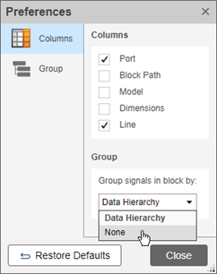
The Preferences dialog box. In the Columns tab, you can select whether or not to display the Port, Block Path, Model, Dimensions, and Line signal properties. In the Group tab, you can choose to group signals by Data Hierarchy or None.

 Functionality being removed or changed

Execution Order display for a selected task no longer highlights virtual blocks and signal lines

Behavior change

When you determine the execution order for a selected task, the virtual blocks and the signal lines are no longer highlighted. For more information, see Control and Display Execution Order.

Execution Order pane displays blocks with different types of constant sample times in separate tasks

Behavior change

The Execution Order pane displays blocks with different types of constant sample times in separate tasks. For example, Simulink blocks with constant sample times [Inf 0] and [Inf Inf] are displayed in two separate tasks indicated by unique Task ID values. For more information about constant sample times, see Constant Sample Time. For more information about execution order, see Control and Display Execution Order.

Component-Based Modeling

Override Model block simulation modes without dirtying parent models

To override the simulation modes of the Model blocks in a model hierarchy without dirtying their parent models:

  1. Configure the top model to simulate in normal mode.

  2. Specify how to override the Model block simulation modes using the new ModelReferenceSimulationModeOverride model parameter.

    • none (default) — Use the simulation modes specified by the Model blocks.

    • all-normal — Use normal mode for all Model blocks.

    • all-accelerator — Use accelerator mode for all Model blocks.

    • specified-models-to-normal — Use normal mode for the Model blocks that reference the specified models.

    • specified-blocks-to-normal — Use normal mode for the specified Model blocks.

  3. To override the simulation modes for specified models or Model blocks, get the model names and block paths using the new pathsToReferencedModel function.

  4. Specify the models or blocks using the new ModelReferenceSimulationModeOverrideScope model parameter.

The override is in effect during each of the simulation phases, including model compilation.

Model blocks that reference protected models do not support simulation mode overrides.

For an example, see Override Model Reference Simulation Modes.

Input bus element ports of subsystems support element specification without additional blocks or bus objects

Starting in R2023b, when you have at least one In Bus Element block that represents an input port of a subsystem, you can:

  • Specify properties of elements at that input bus element port without a block that selects the element or a Simulink.Bus object.

  • Add elements to that input bus element port without adding blocks or specifying a Simulink.Bus object.

Previously, only In Bus Element blocks at model interfaces supported this functionality.

For example, suppose a subsystem receives a bus that contains two elements. An In Bus Element block in the subsystem selects one of these elements. You can specify the properties of the elements regardless of whether an In Bus Element block selects them.
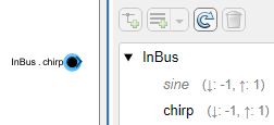
Both elements specify nondefault properties.

For another example, suppose you want to define the interface of a subsystem saved in a subsystem file. An In Bus Element block in the subsystem selects an element from the corresponding port. You can add elements to the port without adding blocks or specifying a Simulink.Bus object.
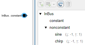
The port contains the selected element and a nested bus, which has three elements with nondefault properties. The nested bus and its elements are not selected by an In Bus Element block.

You can define the interface of the subsystem without cluttering the block diagram with unnecessary blocks. When you reference the subsystem file using a Subsystem Reference block, the hierarchy and properties of the input bus must match the definition at the corresponding port.

To add elements to an input bus without adding blocks to the block diagram:

  1. Double-click the In Bus Element block, or open the Property Inspector and select the block.

  2. In the dialog box or Property Inspector, select the element that you want to contain a new element.

  3. Click the Add element button arrow. Then, select Add element without block.

    The new element is nested under the selected element. The block diagram is unchanged.

To programmatically add elements to the input bus without adding blocks to the block diagram, use the Simulink.Bus.addElementToPort function.

Implicit fixed-step solvers support Simscape and Descriptor State Space blocks inside conditionally executed subsystems

The implicit fixed-step solvers ode1be and ode14x support simulating models with conditionally executed subsystems that contain implicit systems. For example, you can now use an implicit fixed-step solver to simulate a model that contains an enabled subsystem or action subsystem that uses Simscape™ blocks. In prior releases, the software issued an error in this situation.

Implicit systems have continuous states and require an implicit solver. Because triggered subsystems and function-call subsystems do not support continuous states, these types of subsystems cannot contain implicit systems and are not affected by this change.

Promote content preview of active choice to Variant Subsystem automatically and directly navigate to the active variant

Starting in R2023b, Simulink promotes the content preview of the active choice of the Variant Subsystem automatically. Additionally, you can navigate directly inside the active variant by double clicking on the Variant Subsystem block. Previously, to determine and open the active choice, you had to write a script in the openfcn callback of the Variant Subsystemblock.

Activate Variant Parameters from Variant Manager for Simulink support package

When you activate a variant configuration from Variant Manager, the operation activates any variant parameters present in the base workspace or data dictionaries that are associated with the active model components in the model hierarchy.

In the Variant Parameters tab, active variant parameters appear highlighted and inactive variant parameters are grayed out. Point to variant parameters to display a tooltip that shows any additional information related to the activation status. You can find the usage of variant control variables by variant parameters in the model hierarchy table. Right-click the variable in the Control Variables table and select Show usage or Hide usage.

For more information, see Create a Simple Variant Parameter Model.
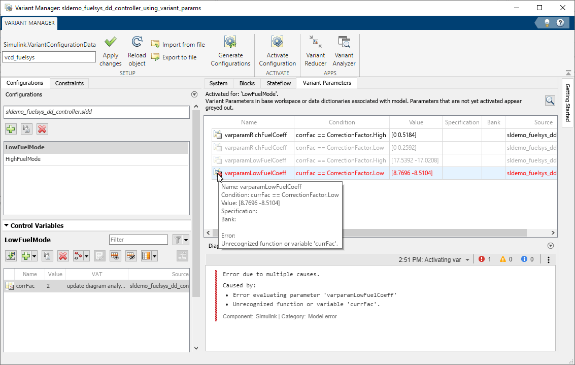
Variant Parameter tab in Variant Manager

Enhancements to the Variant Manager for Simulink support package

  • Remove Variant Subsystem Layer from Reduced Model

    Use the Remove Variant Subsystem Layer option in the Variant Reducer toolstrip to remove the outer layer of a Variant Subsystem block when only one of the choices of the variant subsystem remains active in the reduced model. Variant Reducer retains the active choice block and removes the Variant Subsystem block in the reduced model. The option is enabled by default. See Steps to Reduce Variant Model.

    Variant reducer toolstrip shows the Remove Variant Subsystem Layer option

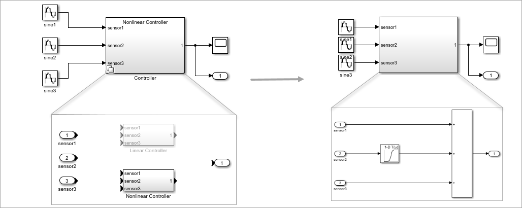
    In this example, after reducing the model for the Nonlinear Controller configuration, the reduced model retains the Nonlinear Controller subsystem and the Controller variant subsystem is removed.

    Reduced model after removing the Variant Subsystem outer layer

  • Exclude Model Files During Variant Reduction

    The Files to exclude option in Variant Reducer now supports specifying Simulink model files (*.slx, *.mdl) to exclude when reducing a model. Previously, the option supported only data files (*.sldd, *.mat).

    For more information, see Steps to Reduce Variant Model.

  • Get Name of Referenced Component Configuration

    Simulink.VariantConfigurationData has a new method, getComponentConfigurationName, that allows you to get the name of the configuration used by a referenced component in a top-model configuration. For example,

    modelName = 'slexVariantManagement';
    openExample(modelName);
    vcd = Simulink.VariantManager.getConfigurationData(modelName);
    vcd.getComponentConfigurationName(ConfigurationName='LinExterHighFid',...
    ComponentName='slexVariantManagementExternalPlantMdlRef');

New edit-time filter functions to find Variant Subsystem blocks

Simulink provides these built-in match filter functions that you can use at edit time when searching models using find_system, find_mdlrefs, and Simulink.FindOptions.

  • Simulink.match.legacy.filterOutCodeInactiveVariantSubsystemChoices — Include Variant Subsystem block choices that are active in simulation or part of generated code when searching a model.

  • Simulink.match.legacy.filterOutInactiveVariantSubsystemChoices — Exclude inactive Variant Subsystem block choices when searching a model.

For more information, see MatchFilter.

Add multiple images to the block mask icon and package them with the model

Starting in R2023b, you can:

  • Add multiple images to the block mask icon using multiple image commands.

  • Package the images with the model using the option Save image files with model.
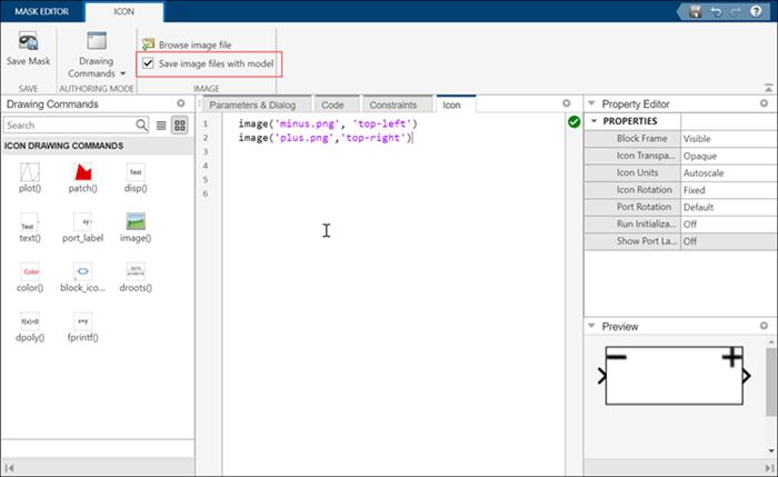
save image with model

Improved performance of models with several Subsystem Reference instances

Previously, when you modified and saved a Subsystem Reference block diagram, the changes propagated to the subsystem file and all the Subsystem Reference instances. Starting in R2023b, to optimize the performance of models, when you modify and save a Subsystem Reference block diagram the changes propagate to the subsystem file and only the visible Subsystem Reference instances. For more information, see Edit and Save Referenced Subsystem.

Trigger an aperiodic partition with multiple events in the Schedule Editor

In the Schedule Editor, you can trigger an aperiodic partition to execute by binding it to a Schedule Event. Starting in R2023b, you can bind multiple events to a single aperiodic partition.

Protected models can support external mode simulation

Starting in R2023b, when a protected model creator specifies that a protected model supports C code generation, the protected model also supports external mode simulation.

For more information about using protected models, see Reference Protected Models from Third Parties.

Support model workspace and mask workspace for variant blocks with startup activation time

Starting in R2023b, you can use mask and model workspace simulate and generate code for variant blocks with startup activation time. With model workspace support, you can have multiple instances of model blocks using variant control parameters as model arguments.

Match ports of variant choices to Variant Subsystem block interface

Starting in R2023b, you can detect inconsistencies and match the interface of the variant choices of the Variant Subsystem block. To enable this, turn off the Allow flexible interface block parameter. If the ports of the choice blocks do not match with the Variant Subsystem block you can either fix the interface by matching the ports, or turn on the Allow flexible interface parameter through the fix-it options reported.

Enhancements to Variant Subsystem block

Starting in R2023b, you can:

  • Display names of the newly created blocks and ports inside a Variant Subsystem block by default. Previously, to display the names of blocks and ports, you had to right-click on the block or port and navigate to Format > Show Block Name > On.

  • Set the name of the variant control label to the name of the variant choice for a newly created Variant Subsystem block in label mode.

  • Delete variant choices permanently in the Variant Subsystem block from the table in the Block Parameters dialog. To delete a choice, select the choice, and click the new delete icon. Previously, to delete a choice you had navigate inside the Variant Subsystem block and delete the choice.

Upgrade advisor check for export-function models

Starting in R2023b, you can check if the model settings to create an export-function model are satisfied. For more information, see Designate Model as Export-Function Model and Satisfy Export-Function Model Requirements. For more information about this check, see Check if the model settings to create an export-function model are satisfied.

 Functionality being removed or changed

convertToVariant, convertToVariantAssemblySubsystem, and variantLegend methods move to Simulink.VariantUtils class

Warns

The convertToVariant, convertToVariantAssemblySubsystem, and variantLegend methods will be removed from the Simulink.VariantManager class in a future release. The method calls continue to work with a warning.

Starting in R2023b, you can access these methods from the new Simulink.VariantUtils class. The convertToVariant method has been renamed to convertToVariantSubsystem in this class.

Simulink.Variant object renamed

Still runs

The Simulink.Variant object has been renamed to Simulink.VariantExpression. Using Simulink.Variant is not recommended and will be removed in a future release.

Invalid root Inport/Outport block connection diagnostic will be removed

Still runs

The Invalid root Inport/Outport block connection diagnostic configuration parameter will be removed and replaced with a Model Advisor check in a future release.

Extraneous discrete derivative signals diagnostic will be removed

Still runs

The Extraneous discrete derivative signals diagnostic configuration parameter will be removed in a future release. Use the Solver Profiler instead.

Change in default behavior of Simulink.VariantManager.reduceModel method

Behavior change

When you reduce a model that contains a VariantSubsystem block using the reduceModel method and if only one choice of the Variant Subsystem remains active after reduction, then the method removes the outer layer of the VariantSubsystem block and moves the block that represents the active choice to the top level in the reduced model. The RemoveVariantSubsystemLayer argument enables this behavior and its value is set to true by default.

New code generation requirement for model reference hierarchies that use fixed-step zero-crossing detection

Behavior change

When you generate code for a model reference hierarchy using Simulink Coder™ or Embedded Coder®, the value of the Enable zero-crossing detection for fixed-step simulation parameter must be the same for the top model and all referenced models in the hierarchy.

Software issues warning for models with no continuous states that have fixed-step zero-crossing detection enabled

Behavior change

Since fixed-step zero-crossing detection became available in R2022a, the software has issued an error when a model enables fixed-step zero-crossing detection but does not contain any continuous states. Starting in R2023b, the software issues a warning instead to support code generation for model reference hierarchies that use fixed-step zero-crossing detection and have one or more models that do not contain continuous states. This change also provides improved support for configuration references for both simulation and code generation workflows.

Fixed-step zero-crossing detection improves the accuracy of simulation results by compensating continuous state values when discontinuities occur during simulation. Enable fixed-step zero-crossing detection for a model that does not have continuous states only when required for code generation. Enabling fixed-step zero-crossing detection for simulation of a model that has no continuous states might affect simulation performance.

lcc-win64 compiler will be removed

Warns

The lcc-win64 compiler will be removed in a future release. For information about supported compilers, see Supported and Compatible Compilers - Windows.

Project and File Management

Source Control API: Interact with Git source control programmatically

You can now programmatically interact with source control.

  • Clone a Git™ repository using the gitclone function.

  • Create a Git repository object using the gitrepo function.

  • Initialize a Git repository using the gitinit function.

  • Create, delete, and switch branches using the createBranch, deleteBranch, and switchBranch functions, respectively.

  • Add files, remove files, and commit changes to a Git repository using the add, rm, and commit functions, respectively.

  • Inspect the commit history in a Git repository using the log function.

  • Display the status of files in a local Git repository using the status function.

  • Fetch or pull new data from remote Git repositories using the fetch or pull functions, respectively.

  • Merge Git branches and revisions into the current branch using the merge function.

  • Publish your local changes to a remote Git repository using the push function.

Project API: Determine whether file belongs to a project

You can now programmatically determine whether a file or a folder belongs to a project by using the matlab.project.isFileInProject function.

Model Comparison: Improved reports for MATLAB Function blocks comparison

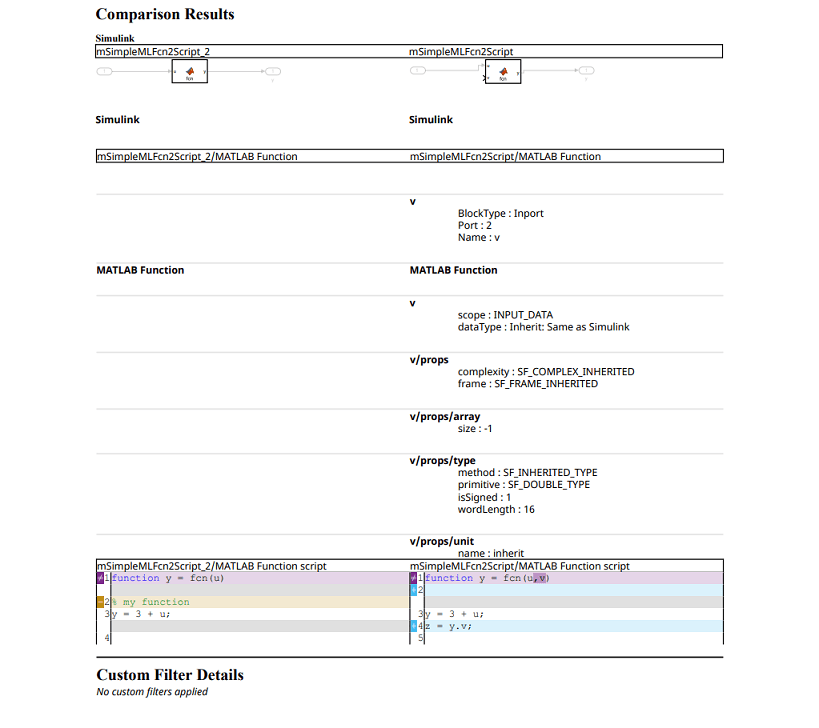
Model comparison publishable reports now use MATLAB Editor syntax highlighting for script parameters in MATLAB Function blocks. You can now more easily understand changes in MATLAB Function blocks. The report highlights and flags modified lines with the comparison icons , , and .

Model comparison report that shows a MATLAB Function block comparison.

Upgrade Advisor API: New property to disable backup file generation during model upgrade

By default, the upgradeadvisor function generates backup copies of models during the upgrade process. Starting in R2023b, you can disable the generation of backup files during a model upgrade using the EnableBackups property. For more information, see Programmatically Analyze and Upgrade Model.

Source Control in MATLAB Online: Perform source control operations using unified panel

In MATLAB Online™, you can use the Source Control panel to see all active source control repositories, manage modified files, and perform source control operations.
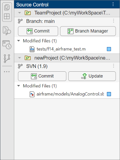
Source Control panel showing two repositories. The first repository is under Git source control and the second is under SVN source control.

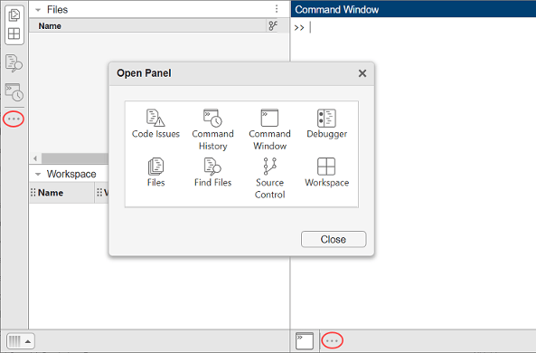
To open the Source Control panel, use the Open more panels button (three-dot icon) in the sidebar.

MATLAB Online desktop with the Open more panels buttons circled in the left and bottom sidebars. The Open Panel dialog box shows the available panels.

Source Control in MATLAB Online: Expanded support for Git workflows

MATLAB Online now provides expanded support for Git workflows:

  • Adding and managing Git submodules

  • Sharing to GitHub®

  • Initializing Git repositories

  • Shallow cloning Git repositories

Projects in MATLAB Online: Added support for team collaboration workflows

Projects in MATLAB Online now provide support for the following team collaboration workflows:

  • Creating referenced projects from project folders

  • Adding source control to existing projects

  • Managing project labels and custom tasks using Project Settings

  • Displaying shadowed files on project startup

  • Upgrading projects using Project Upgrade

Project Examples: Identify and run tests in projects

This example shows how to use labels to identify tests in a project and how to create test suites from project test files interactively and programmatically. For large projects under source control, the example demonstrates how to run a subset of tests to reduce qualification runtime. For more information, see Identify and Run Tests in MATLAB Projects.

Design Evolution Manager in MATLAB Online: Active evolution automatically records changes made to project files

In previous releases in MATLAB Online, changes to project files were only synced to an evolution when you clicked Update Evolution. In R2023b, changes to project files are automatically recorded by the active evolution.

In MATLAB Online, when you finish making changes to project files in an evolution, you can lock the evolution to prevent further changes to project files in that evolution. You can still edit metadata, such as the name of the evolution or notes that you add to the evolution.

In MATLAB Online, if you make changes to project files when the Design Evolution Manager app is closed, you now have the option to save changes to the project in the evolution when you next open the app.

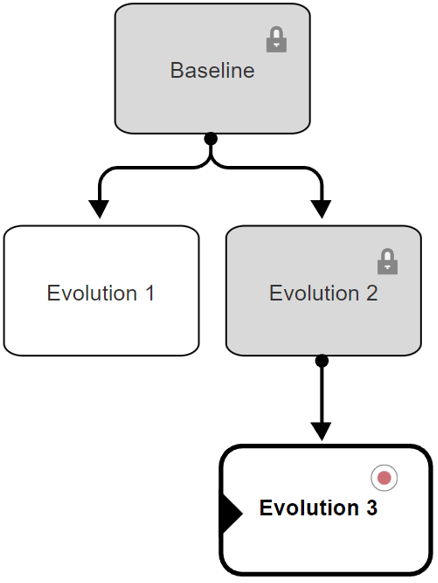
For example, in this evolution tree, the current files indicator marks the evolution whose files are currently open in the project, and the record indicator marks the active evolution. Project files in locked evolutions cannot be edited.

Evolution tree. The Baseline evolution is at the top and locked. Baseline has 2 child evolutions: Evolution 1 and Evolution 2. Evolution 2 is locked. Evolution 2 has a child evolution called Evolution 3. Evolution 3 is the active evolution and is the version of files currently open in the project.

Design Evolution Manager in MATLAB Online: Merging and arbitrary comparison workflows

The Design Evolution Manager app in MATLAB Online has improved comparison and merge workflows:

  • In previous releases, you could only compare evolutions that had a parent-child relationship. In R2023b, you can compare any two evolutions in the evolution tree.

  • You can now compare any two files in different evolutions, even if the files have different names.

  • You can use the integrated Comparison tool to merge differences from an evolution into the active evolution.

 Functionality being removed or changed

XML comparison type for visdiff function will be removed

Warns

The XML comparison type for the visdiff function will be removed in a future release. Overriding the default comparison type by specifying "xml" will not be supported in a future release. In R2023b, scripts that use visdiff(filename1,filename2,"xml") warn.

No compression when you save Simulink models

Behavior change

Starting in R2023b, to reduce the size of Git repositories that contains Simulink models, Simulink no longer applies compression during the save operation. For more information, see Set SLX Compression Level.

Getting parameters of the default block diagram is no longer supported

Errors

Starting in R2023b, getting parameters of the default block diagram is no longer supported. In R2023b, when parameter is the name of a block diagram parameter, scripts that use get_param(0,parameter) error.

Data Management

New section in the Simulink data dictionary containing architectural data

In R2023b, a new architectural data section is added to the Simulink data dictionary. This section of the dictionary stores shared definitions used in the Simulink and architecture model interfaces, such as port interfaces, data types, and system wide constants as well as their platform properties. You can manage architectural data with the Architectural Data Editor and the Simulink.dictionary.ArchitecturalData programmatic interfaces. This new architectural data section allows users to adhere to best practices for data management and it gives a seamless user experience by managing all architectural data in one editing tool.

Type Editor docked in model window

When you open the Type Editor from a model, the Type Editor is docked as a pane in the model window.
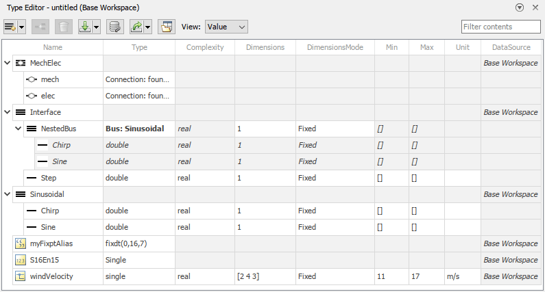
Docked Type Editor with simplified buttons and layout

This integration lets you view where a type is used in your model. For example, you can click a type in the docked Type Editor to highlight the blocks that use the type.
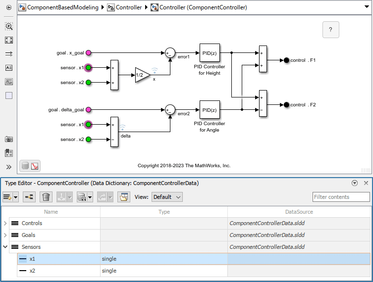
The In Bus Element blocks that select sensor.x1 are highlighted because the Type Editor has the corresponding x1 bus element object selected.

To open the Type Editor in a standalone window, click the Open standalone Type Editor button.

For more information, see Type Editor.

Simulink.Parameter object now supports strings

Simulink.Parameter objects now support string scalars as values. For example:

P1 = Simulink.Parameter("abc");
P2 = Simulink.Parameter;
P2.Value = 'xyz'; 

Signal Editor tool updates

The look and feel of the Signal Editor tool has changed. Changes include:

  • Signal Editor icons and layout have changed.
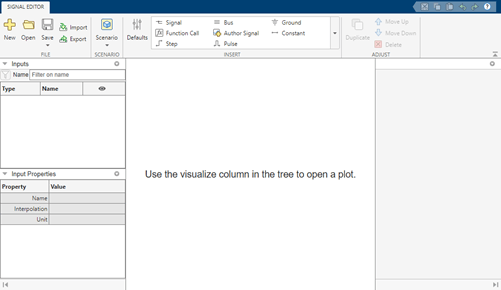
    Signal Editor tool default

    You can customize this layout by dragging and dropping panes and hiding panes.

  • Continue to add scenarios and signals as you did in releases prior to R2023b. To edit or view the plot of a signal, double-click the hide icon (Signal Editor eye for plotting). The Edit tab opens. Notice that signal properties are now on the right of the canvas.
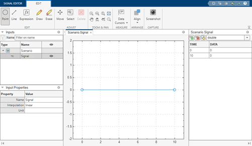
    Signal Editor tool hide

    To close the Edit tab and return to the Signal Editor tab, double-click the show icon (Signal Editor tool show).

  • To start drawing signals, double-click the hide icon Signal Editor eye for plotting. In the plot canvas, you can begin adding signal data points. Previously, you clicked Draw Signal to enter the drawing mode.

  • In the left side Inputs section, you can now select multiple items simultaneously and perform actions on them.
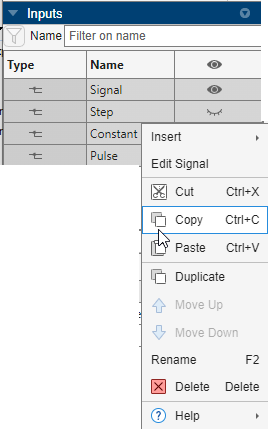
    Signal Editor multiple signal selections and right-click context menu

    For example, you can:

    • Select multiple signals and edit the input properties for multiple signals at the same time.

    • Create the same signal for multiple scenarios.

  • In the tabular editing pane, you can cut, copy, and paste with Excel® spreadsheets.

  • These icons have changed.

    Action

    Old Icon

    New Icon

    Function Call

    Author Signal

    Duplicate

    Delete

    Insert row

    Delete row

    Replace signal data using MATLAB expression

    Erase

    Fit to view (Space)

    Data Cursors

    Align

Root Inport Mapper updates

The Root Inport Mapper tool Check Map Readiness menu has these changes:

  • The default behavior of the Check Map Readiness button now defaults to the last Check Map Readiness option selected.

  • When you click Apply to Model, the status now displays in the Status column of the Scenarios panel.

  • Option names and icons have changed.

    Old Option and IconNew Option and Icon

    Map All ()

    All Scenarios ()

    Map Selected ()

    Selected Scenarios ()

    Map Unconnected ()

    Unconnected Scenarios ()

    Map Failed ()

    Failed Scenarios ()

    Map Warned ()

    Scenarios with Warnings ()

Support for MDF format

The Signal Editor and Root Inport Mapper tools now support reading the MDF format with the Simulink.io.MDF reader class. The Simulink.io.MDF class requires a Vehicle Network Toolbox™ or Powertrain Blockset™ license.

For more information, see Import Custom File Type and Create Custom File Type for Import to Signal Editor.

Mismatched unit detection for model arguments

The software now checks for equivalent unit values when a model argument definition and value have units. At a component boundary, the software detects and reports a warning when these units are mismatched. For more information, see Mismatched Units Detected Between Model Argument Definition and Value.

Support for library dictionaries in Subsystem Reference

Subsystem Reference now supports using data dictionary attached to library blocks. When you add a library block to a subsystem file, the data dictionary attached to the library becomes available to the subsystem file. If you refer to the subsystem file from a model using a Subsystem Reference block, the library dictionary is available within the Subsystem Reference block boundary only.

 Functionality being removed or changed

More efficient check and error reporting behavior for data consistency check

Behavior change

Previously, when a model in a hierarchy was compiled during a model update, Simulink ran a data consistency check on the model if the model was configured to enforce data consistency (EnforceDataConsistency set to the default 'on'). In R2023b, these models are all checked for data consistency when the top model in the hierarchy compiles.

While there is no change in the errors that the consistency checker detects, you might see a change in how the errors are reported. Previously, you might only see a subset of consistency errors in the hierarchy if an error detected below the top model stopped the model update. In R2023b, when the top model compiles, the consistency check reports errors from multiple levels of the model hierarchy at the same time.

For more information on data consistency checks, see Data Consistency in Model Hierarchy.

Simulink.ValueType objects do not override description of parent

Behavior change

When you specify a Simulink.ValueType object as the data type of a Simulink.Signal, Simulink.Parameter, or Simulink.BusElement object, the value type object no longer overrides the description of the parent object.

Block Enhancements

Data Store Memory: Access scoped Data Store Memory blocks across the model hierarchy

Starting in R2023b, a subset of Simulink blocks from inside a referenced model can access the data stored in a Data Store Memory block defined at a higher level in the model hierarchy. These blocks include Data Store Read block, Data Store Write block, S-Function block, MATLAB Function block, MATLAB System block and Chart (Stateflow) block. To allow these blocks to access the data stored in the Data Store Memory block at a higher level in the model hierarchy:

  • Place a Data Store Memory block inside the referenced model. For more information about supported locations of the Data Store Memory block, see Description in Data Store Memory.

  • In the Data Store Memory block dialog box, select Data store reference.

  • On the Signal Attributes tab, specify the Data type, Dimensions and Signal type. When you select Data store reference, these options are not available: Inherit for Data type, -1 for Dimensions and auto for Signal type.

To configure a data source reference for code generation, see Code Generation for Data Store References (Simulink Coder).

Conditional display of the Sample time parameter in certain blocks

These blocks no longer display the Sample time parameter in the block parameters dialog box by default:

The Sample time parameter is visible in the block parameters dialog box only if you set the sample time to a value other the default (-1) either programmatically or in an existing model. For more information, see Blocks for Which Sample Time Is Not Recommended.

Signal Editor block updates

The Signal Editor block dialog box has these updates:

  • In the Signal properties section, the new Apply signal properties to all signals check box lets you apply the specified signal properties to all signals.

  • When you pause on the Active scenario parameter, a tooltip displays the Name property of the data set object. If the block is converted from a Signal Builder block using the signalBuilderToSignalEditor function, the Name property is the same as the Signal Builder block Group name.

Weighted Sample Time and Weighted Sample Time Math blocks update

The Weighted Sample Time and Weighted Sample Time Math blocks now support:

  • Additional output types

    • double

    • single

    • int8

    • uint8

    • int16

    • uint16

    • int32

    • uint32

    • int64

    • uint64

    • fixdt(1,16,0)

    • fixdt(1,16,20,0)

  • Fixed point as a new option to the Mode parameter, which enables the fixed-point parameters:

    • Signedness

    • Scaling

    • Word length

    • Slope

    • Bias

    • Data type override

signalBuilderToSignalEditor function update

The signalBuilderToSignalEditor function now supports virtual buses. If the original Signal Builder block contains a virtual bus output port, signalBuilderToSignalEditor returns a handle to a Subsystem that has a virtual bus output port.

Use the customizable Display block to model displays in real systems

Model displays in real systems, such as the odometer display in your car, using the customizable Display block.

The Display block connects to a signal in your model and displays its value during simulation. When you use the Display block in the Customizable Blocks library, you can customize the appearance of the block to look like a real display in your system.

  • Add a background image or choose a background color.

  • Add a foreground image.

  • Choose from a list of WYSIWYG (what you see is what you get) fonts that look the same on all platforms.

  • Change the font size.

  • Change the text color.

  • Change the text position within the block.

  • Make the text bold, italic, or underlined.

Use the Display block with other dashboard blocks to build an interactive dashboard of controls and indicators for your model.

For more information about the Display block, see Custom Display.

Open dashboard panel in new window

You can now open a dashboard panel in a new window. You can minimize and restore the new window containing the panel separately from the model window. From the panel window, you can run, pause, stop, and step through the simulation.

To open a dashboard panel in a new window, select the panel. In the Simulink Toolstrip, on the Panels tab, in the Manage section, click Open In New Window. Alternatively, select the panel and pause on the ellipsis that appears. In the action menu that expands, click the Open In New Window button .

Note

If a panel contains Dashboard Scope blocks, you cannot open the panel in a new window during simulation. To open the panel in a new window, stop the simulation.

If the panel has multiple tabs, the panel with all its tabs opens in a new window.

To return the panel to the model canvas, in the panel window toolstrip, click Open in canvas .

For more information about opening a panel in a new window, see Open Panel in New Window.

IC block row-major support update

The IC block now supports code generation for row-major array layout.

Permute Matrix block row-major support update

The Permute Matrix block now supports row-major algorithms and code generation for row-major array layout.

Enhancements to C Caller and C Function blocks and custom code integration

In R2023b, C Caller and C Function blocks and custom code integration have these enhancements.

  • When you integrate a custom code library, if you are using the MinGW® compiler as your MEX compiler, you only need to include the DLL (.dll) format of the library in the configuration for your model. Before R2023b, the software checked for both the .dll and the .lib format. If you are using Microsoft® Visual C++® (MSVC) as your MEX compiler, you still need to include both formats. For more information on how to include libraries, see Libraries. For more information on selecting a MEX compiler, see Change Default Compiler.

  • C Caller and C Function blocks support the pointer to array type and aliases as function arguments and global variables. Variables of this type point to an entire array. This example shows how to declare variables of this type. In this example, ptr is a pointer to an array of five integers. The ptrType type is used to create ptr2, which is also a pointer to an array of five integers.

    int (*ptr)[5];
    
    typedef int (*ptrType)[5];
    ptrType ptr2;

  • Before R2023b, global and static variables in custom code retained their values between simulation runs, causing unexpected results. Starting in R2023b, global and static variables in custom code are reset between simulation runs.

  • Before R2023b, the software did not support calling custom C/C++ functions declared with static inline. Starting in R2023b, you can call static inline C/C++ functions in blocks with custom C/C++ code.

Constant block supports Simulink.ValueType object data type

Constant blocks now support Simulink.ValueType objects as data types. Each value type specified for a Constant block must have fixed dimensions because Constant blocks do not support variable-size signals.

When you specify a value type as the data type of a Constant block, the value type overrides the minimum and maximum specified by the block and the data type of the constant value. The value type validates the dimensions, complexity, and unit of the constant value. When these properties do not match, the software issues a warning or error.

For example, suppose a Constant block has these settings:

  • Constant value set to a Simulink.Parameter object with a unit of ft/s

  • Output data type set to a Simulink.ValueType object with a unit of m/s

During model compilation, the software issues a warning about the mismatched units. The Constant block uses ft/s as the unit.

For another example, suppose a Constant block has these settings:

  • Constant value set to [2 3]

  • Output data type set to a Simulink.ValueType object with dimensions of 1

During model compilation, the software issues an error about the mismatched dimensions. Mismatched complexity also results in an error.

The Constant block does not use the description of the value type.

For more information about value types, see Specify Common Set of Signal Properties as Value Type.

Bus Selector block dialog box redesigned

The Bus Selector block dialog box has a new, streamlined design with additional functionality.

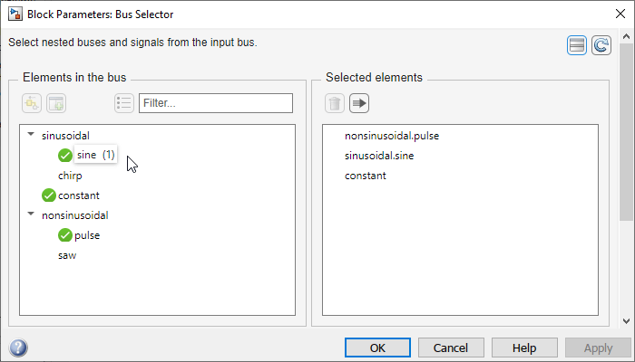
  • In the Elements in the bus list, a green check mark icon appears next to selected output elements.

  • In the Elements in the bus list, when you pause on a selected output element, a parenthetical displays how many times the Bus Selector block selects that element.

  • Filtering supports regular expressions by default.

  • You can toggle between vertical and horizontal layouts.

By default, the dialog box opens in the new vertical layout, with the selected elements under the list of elements in the bus.
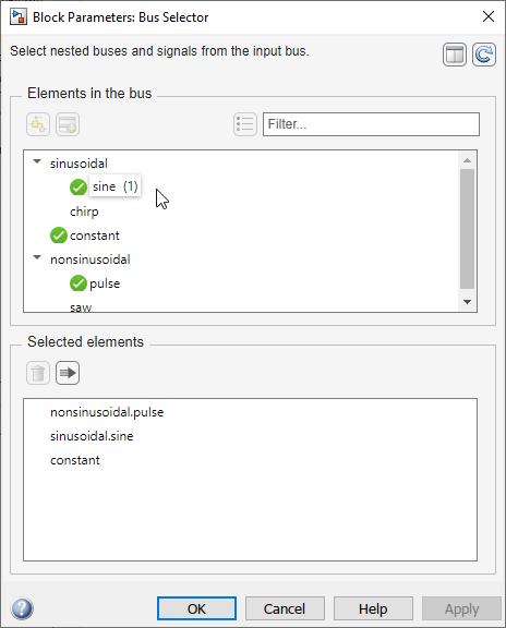
Bus Selector block dialog box with vertical layout

To view the elements in the bus and the selected elements side by side, click the Change layout button.

Bus Selector block dialog box with horizontal layout

The horizontal layout more closely mimics the previous Bus Selector block dialog box design.

The previous functionality remains.

  • Filter the elements in the bus by name with or without regular expression — Enter the search term in the Filter box.

  • Show filtered results as a flat list — Click the Show filtered results as a flat list button.

  • Find source of elements in the bus — Click the Highlight source blocks button.

  • Refresh list of elements in the bus — Click the Refresh button.

  • Select output elements — Select the desired output elements from the Elements in the bus list. Then, click the Select elements button (vertical layout) or the Select elements button (horizontal layout).

  • Move selected elements up or down — Drag elements in the Selected elements list to a different position in the list.

  • Remove selected elements — Select the elements to remove from the Selected elements list. Then, click the Remove button.

  • Output selected elements as a virtual bus — Click the Output as virtual bus button.

Parameter Writer block supports invisible masked subsystem parameters

A Parameter Writer block can now write to a masked subsystem parameter that is enabled regardless of whether the mask dialog box displays the parameter.

Tunability of mask parameters that are modified or created in mask initialization is retained in the generated code

Before R2023b, if a model contained blocks with mask initialization commands that modified a mask dialog parameter or created a new variable in the mask initialization, and if that parameter or variable is referenced in a child block, the values of the mask parameter or variable were in-lined in the generated code. The parameters were not tunable even if they referred to a workspace variable.

Starting in R2023b, expressions corresponding to mask parameters referenced in the child block now appear in the generated code even if the parameters are created in mask the initialization section of the top-level mask thus retaining tunability. The tunability of these parameters is retained only if the mask initialization code is created using a mask callback file and the parameter value is defined in the specified format. See Preserve Tunability of Parameters That Are Modified or Created in Mask Initialization for more information.

Preserve tunability of mask parameters whose values are referencing a subarray

When the value of a mask parameter is a MATLAB array, and you set one of the array elements to the value of an underlying child block parameter, the tunability of the mask parameter is preserved in the generated code.

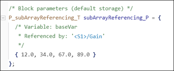
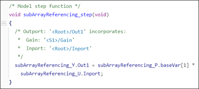
For example, consider a masked subsystem containing a Gain block as a child block. The masked subsystem has a tunable parameter named customGain whose value is set to a workspace variable baseVar. The value of baseVar is a MATLAB array. The value of Gain parameter in the Gain block is set to an element of customGain using the subscript operator. In this scenario, tunability of customGain is preserved because the variable baseVar is retained in the generated code.
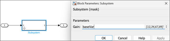
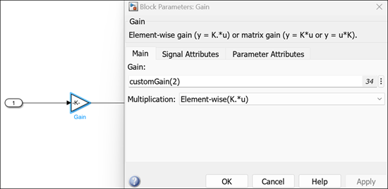
Masked subsystem block referring subarray

Child block referring the tunable parameter

The generated code is:

Array elements listed in the data file of the generated code

Model step function containing the expression

Observe that the generated code contains the expression for the tunable parameter.

Improve tunability for mask enumeration parameters popup and radio button

Starting in R2023b, you can tune the mask radio button parameter by providing a list of options for simulation time tunability or an enumeration class for code generation tunability.

  • Use List of options to create options for the radio button with display names and the values. You can enter numeric or string values as options.

  • Create a new enumeration class with name, member names and values or reference an external enumeration class derived from Simulink.IntEnumType or Simulink.Mask.EnumerationBase. You can only associate numerical values to the radio button using an enumeration class.

  • Associate a workspace variable with a mask radio button parameter.

See Tune Mask Enumeration Parameters - Popup and Radio Button for more information.
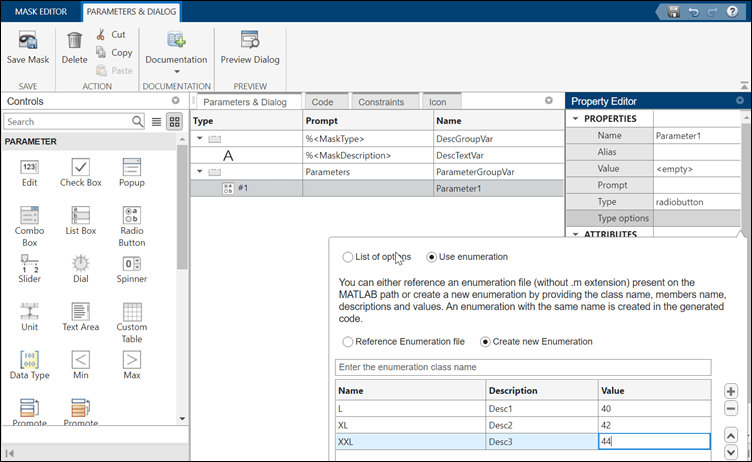
tunable radio button

Improvements to Graphical Icon Editor

Starting in R2023b, you can:

  • Render multiple variations of the same block icon using layers. Each variation is visible based on conditions on the block parameters. The variations are saved in a single file. For example, you may want to increase the number of switch ports based on a block parameter. Use layers to create multiple variations of the block icon for each scenario. See Add Dynamic Behavior to Masked Icons for more information.
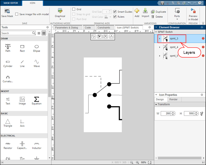
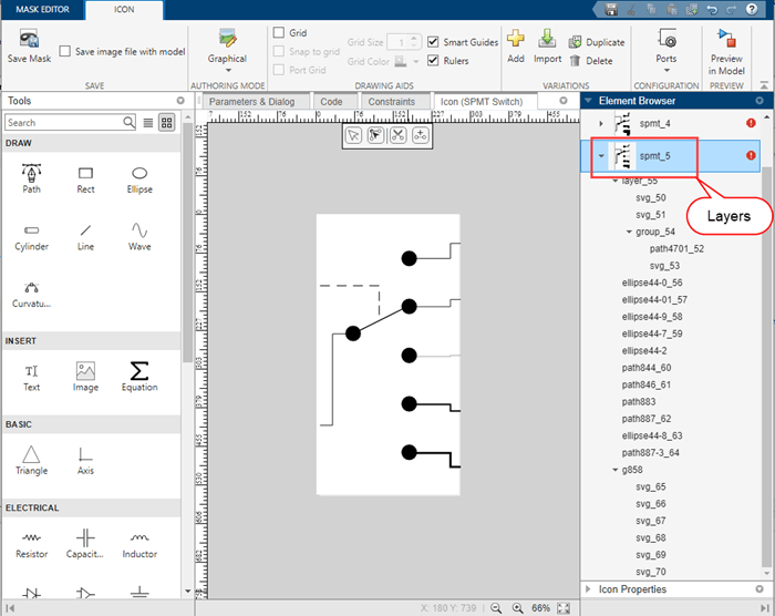
    layers

    variation of the icon

  • Package icon image files with the model using the option Save image files with model in the Graphical Icon Editor.
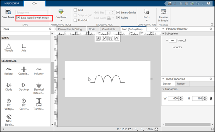
    save image

  • Select arrow heads based on type, fill, and size. Previously you had to choose the arrowhead style from a long list of 250 styles. You can now choose from a drop-down list, toggle to fill the arrowhead, and select the size of the arrowhead.
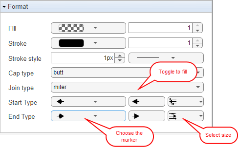
    arrow head choice

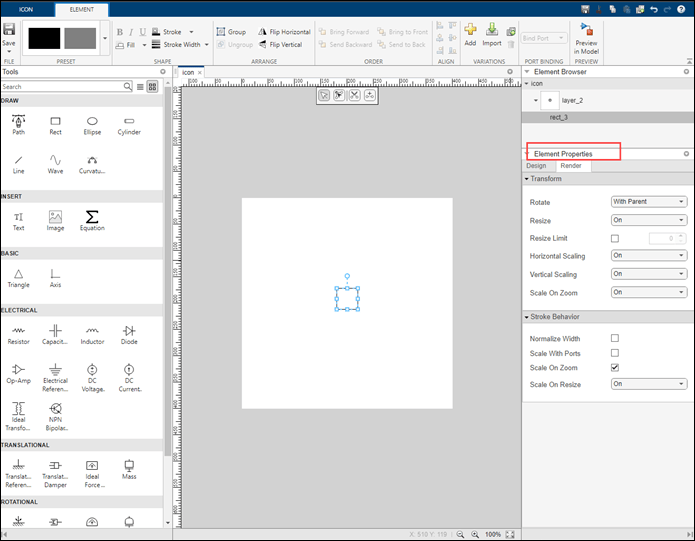
  • Easily access canvas properties and element properties. The options are listed based on the icon and element context. For the icon, you have options to set the frame of the icon and rotate or resize the icon. For each element in the icon, you can rotate, resize, and set the stroke of the element. Previously, these options were under Simulink properties in the toolstrip. Now these options are available in the Icon Properties and Element Properties section.
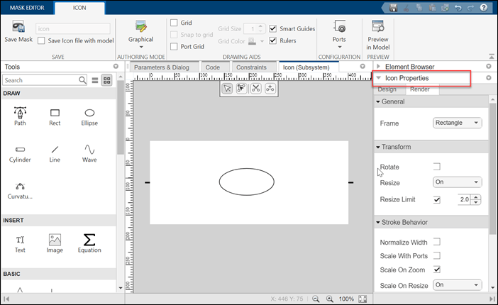
    icon properties

    element properties

  • Use the option Port Grid to align the elements of the canvas to ports.
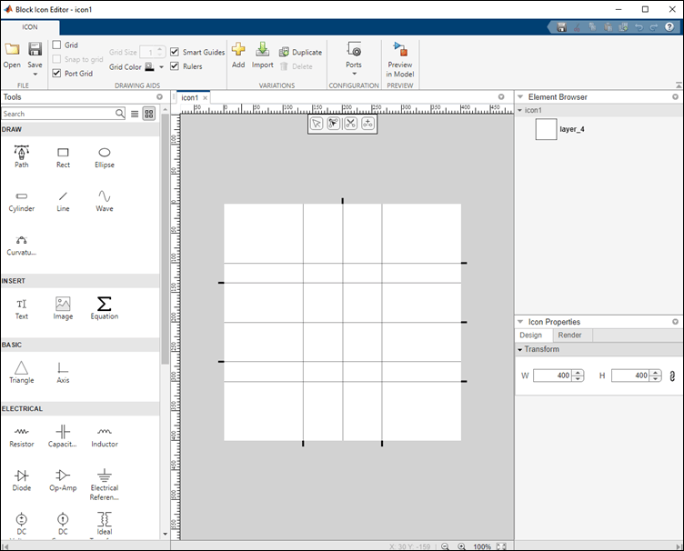
    port grid

  • Find port styling information for Simscape blocks in the Graphical Icon Editor.
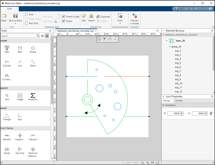
    port styling

Neighborhood Processing Subsystem block supports one-dimensional array input

Starting in R2023b, the Neighborhood Processing Subsystem block supports using one-dimensional arrays as input matrices. Use the Neighborhood Processing Subsystem block to divide a sequence of data into sections and process each section separately.

Customize System object icon using Mask Editor

You can now use the Mask Editor to create and edit the mask icon of a MATLAB System block. The Mask Editor helps you to customize a block icon with descriptive text, images, equations, and graphics using the Graphical Icon Editor or mask drawing commands and save time in writing code. When you use the Mask Editor, all mask definitions are stored in an auxiliary XML file resulting in faster loading of the System object™. For more information on icon customization using Mask Editor, see Customize MATLAB System Icon and Dialog Box Using Mask Editor.

If you previously customized the mask of a MATLAB System block using the getIconImpl function in a MATLAB System class file, then you can migrate these mask definitions to an auxiliary XML file. Launch the Mask Editor of the MATLAB System block and save the mask. You will get a message:

  • Click Save to save the existing and new dialog and icon customizations to a new XML file. This removes all the dialog and icon customization related functions from the existing MATLAB System class file.

  • Click Cancel to continue using the dialog and icon customizations from the MATLAB System class file. Any customizations done using the graphical interface are discarded.
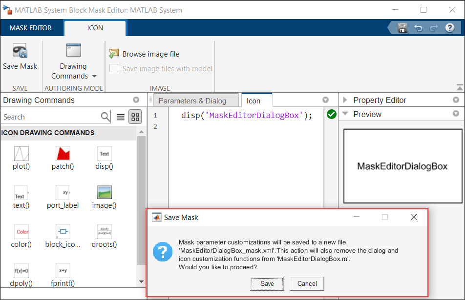
View of MATLAB System Block Mask Editor. The left pane displays the Icon drawing commands. The middle pane displays when a MATLAB System mask icon is modified and saved, a warning message is displayed.

Faster loading of System object blocks

Loading of MATLAB System objects into Simulink shows improved performance as the mask definitions of the System object blocks are now saved in an auxiliary XML file.

For example, if you load ten MATLAB System object blocks, performance in R2023b is approximately 2.5x faster than in R2023a.

The approximate reporting times are:

R2023b: 3.5 s

R2023a: 9 s

The reporting was timed on a Windows® 10, AMD EPYC 74F3™ 24-Core Processor @ 3.19 GHz test system by calling the tic and toc functions for ten MATLAB System object blocks: TPC Decoder, TPC Encoder, Timer Block, Wavetable Synthesizer, Audio Oscillator, Octave Filter Bank, OFDM Modulator, Viterbi Decoder, Linear Equalizer, and Decision Feedback Equalizer.

You can get this performance gain for your System objects by migrating the mask definition of the System object block from the MATLAB System class file to an auxiliary XML file. For more information on migrating, see Migrate Existing Icon and Dialog Box Customizations to Mask Editor on Customize MATLAB System Icon and Dialog Box Using Mask Editor.

From Spreadsheet block update

The From Spreadsheet block now searches for the spreadsheet file within the current folder if it cannot find the spreadsheet file in the full path provided. This change enables Simulink Compiler™ standalone executables containing From Spreadsheet blocks to find spreadsheet files. In previous releases, the From Spreadsheet block did not look for spreadsheet files in current folders.

Code generation support for FMU Import block

The FMU Import block now supports code generation for FMI 1.0 and FMI 2.0.

Python Importer now supports Python functions specified within Python classes

You can now use Python Importer wizard to import Python® functions that are defined within Python classes. Python Importer generates a MATLAB System object for each of the selected functions and creates a block library containing MATLAB System blocks that implement each of the generated System object in Simulink. When a class constructor method is specified with the Python class, the Python Importer defines the class constructor arguments as non-tunable properties of the generated System object. The properties appear as non-tunable parameters of the corresponding MATLAB System block in Simulink.

For example, consider the following Python class:

class room:
    
    def __init__(self, length, breadth, height):
        self.length = length
        self.breadth = breadth
        self.height = height
    
    def volume(self):
        result = self.length * self.breadth * self.height
        return result

    def wallarea(self):
        result = 2 *(self.length * height + self.breadth * height)
        return result
Python Importer enables you to import the functions volume and wallarea. You can also set the port and parameter specifications during import. In this example, length, breadth, and height specified in the class constructor are imported as parameters.
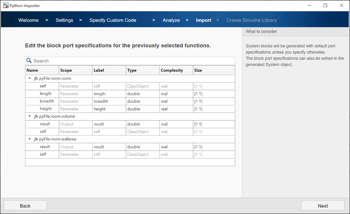
Python Importer window to specify parameters and port specifications

The Python Importer generates a block library with a MATLAB System block for each of the imported functions. The attributes of the class are defined as non-tunable parameters of the block. In this example, length, breadth, and height can be set in the Block Parameters dialog.
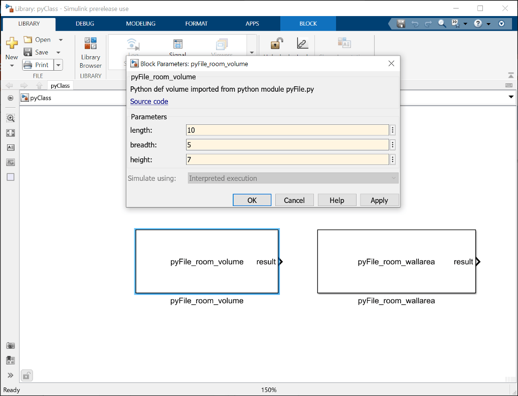
Generated Simulink block library and parameters

FMI 3.0 support for FMU Import block

Starting in R2023b, the FMU Import block supports the following FMI 3.0 features:

  • Introduction of new integer and float data types.

  • Native support for vectors and matrices.

  • Event mode support for co-simulation mode.

  • Binary data type support.

Enumeration data type support for FMU Import block

Starting in R2023b, the FMU Import block supports Enumerated data type for block input and output. You can directly connect enumeration signals to FMU Import block without conversion to int32 data type. You can also use the FMU Import dialog to customize the names of enumeration objects.

Discrete input value changes in Model Exchange FMU triggers event mode

In R2023b, the FMU Import block detects discrete input value changes for Model Exchange FMU and triggers event iteration.

Directly launch external debugger for debugging S-function from Simulink

You can now directly launch an external debugger for debugging S-Function and S-Function Builder blocks from Simulink without manually configuring the external debugger to connect to Simulink. To launch the external debugger, go to the Debug tab in Simulink and select Set Breakpoints in Custom Code option.
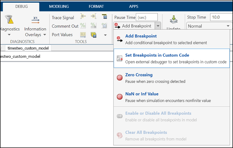
Launch external debugger from the debug tab of Simulink using Set Breakpoints in Custom Code option from drop-down

The Select Entities to Debug dialog box list the entities that can be debugged. The custom C/C++ code defined for a model in the Simulation Target pane of the Model Configuration Parameters dialog box is listed under Model Custom Code and the S-function and S-Function Builder blocks are listed under S-Function Blocks. Select the entities that you want to debug and move them to Selected Entities.
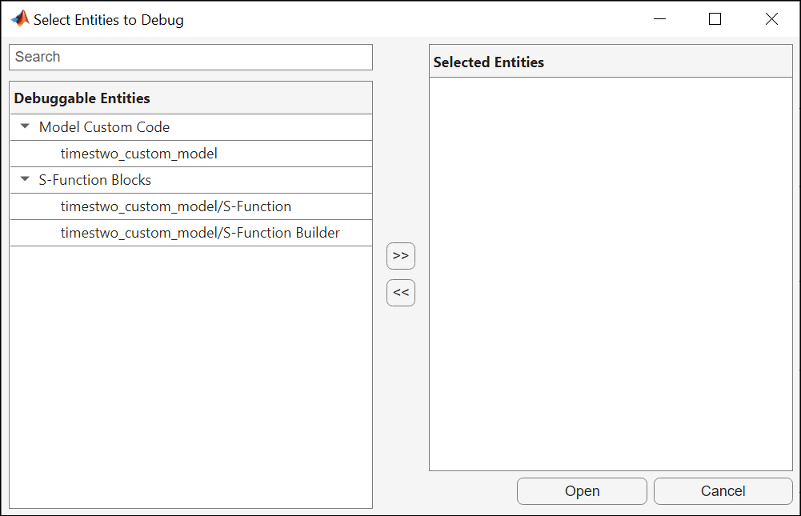
Dialog box that lists entities that can e debugged

Click Open to launch the external debugger.

Rate Limiter Dynamic simulates more accurately for initial input signal

Starting in R2023b, the Rate Limiter Dynamic block simulates more accurately for the initial input signal. If the expected output sample is nonzero, you will now get the expected value based on the initial condition. In releases prior to R2023b, initial output samples were always 0.

 Functionality being removed or changed

New warning identifies Derivative blocks with inputs that do not have continuous sample time

Warns

A new warning identifies Derivative blocks that have input signals with discrete or fixed-in-minor sample time. When the input to a Derivative block does not have continuous sample time, the block might produce incorrect or unexpected results. The software issues a warning at compile time for each block that requires attention.

To resolve the warning, you can:

  • Modify the model so that the input signal has continuous sample time.

  • Solve the system by integrating instead of differentiating by using block that integrate, such as the Integrator block, instead.

  • Implement the derivative using another block, such as the Transfer Fcn block or the Discrete Derivative block.

For more information, see Derivative.

Connection to Hardware

Support to download Android support package on Linux operating system

Starting R2023b, you can now download the Simulink Support Package for Android® Devices on devices with the Linux® operating system.

Capture JPEG images from ArduCam 2 megapixel Mini Module Camera Shield with OV2640 sensor

This release introduces the OV2640 Camera Sensor block, which you can use to capture JPEG images from the ArduCam 2 megapixel Mini Module Camera Shield with an OV2640 sensor. You can also specify the resolution of the JPEG image that the block outputs.

Support for handling hardware interrupts from ADC and PWM peripherals and event systems on Arduino SAMD hardware

The Simulink Support Package for Arduino® Hardware now supports handling hardware interrupts generated by the ADC and PWM peripherals for the SAMD family of Arduino hardware. Earlier releases supported handling of hardware interrupts only from external pins. This release also adds support for event system (EVSYS) that allows autonomous, low-latency, and configurable communication between the peripherals.

  • Hardware Interrupt — Use this block to trigger a downstream function-call subsystem from an interrupt service routine.

  • PWM — Use this block to generate a square wave on the specified output pin of the Arduino SAMD hardware.

  • Analog Input — Use this block to read the ADC register value at the specified pin of the Arduino SAMD hardware.

You can access these new blocks from the Advanced > SAMD library.

Send and receive data from HTTP server using HTTP Client block on Raspberry Pi hardware

This release introduces the HTTP Client block that you can use to send and receive data from the remote server using the HTTP protocol.

Support for external mode for Raspberry Pi — Robot Operating System (ROS)

The Raspberry Pi® Blockset now supports using the external mode (Monitor and Tune) workflow to tune parameters and monitor a Simulink generated ROS node within a ROS network.

Support for secure MQTT communication between server and client on Raspberry Pi hardware

The Raspberry Pi Blockset now supports establishing a secure MQTT connection between the server and a client using a certificate-based authentication. You can now configure MQTT parameters such as port number and specify an SSL certificate to authenticate the connection to the server.

MATLAB Function Blocks

Support for unbounded arrays

MATLAB Function blocks now support unbounded arrays for output and input variables. To specify unbounded output variables, select the Variable size property for the variable and set the dimension in Size to Inf. Input variables inherit their size. See Unbounded Variable-Size Signals, Declare Variable-Size MATLAB Function Block Variables, and Specify Size of MATLAB Function Block Variables.

coder.mustBeConst: Validate that value is compile-time constant

Starting in R2023b, you can use the coder.mustBeConst validator inside an arguments block to validate that the value of a function argument is a compile-time constant.

Code generation for more toolbox functions

In R2023b, you can generate code for many additional toolbox functions and objects. For a list of all functions and objects that are supported for code generation, see:

These are links to the release notes of some toolboxes that added code generation support in R2023b:

Computer Vision Toolbox

See Generate C and C++ Code Using MATLAB Coder: Support for functions (Computer Vision Toolbox).

Image Processing Toolbox

See C Code Generation: Generate code from additional functions using MATLAB Coder (Image Processing Toolbox).

ROS Toolbox

See C++ Code Generation Support Enhancement for ROS 2: Deploy ROS nodes to target hardware using MATLAB Coder (ROS Toolbox).

Signal Processing Toolbox

See C/C++ Code Generation Support: Code generation for spectral analysis and signal modeling (Signal Processing Toolbox).

Statistics and Machine Learning Toolbox

See:

Modeling Guidelines

Guideline for check safety-related diagnostic settings for Stateflow

These high-integrity system modeling guidelines have been modified or removed.

Modeling GuidelinesDescription
hisl_0012: Usage of conditionally executed subsystemsRemoved
hisl_0024: Inport interface definitionNote includes information about capturing reusable specifications as a Simulink.ValueType object and specifying the data type for the In Bus Element and Out Bus Element blocks.
hisl_0039: Configuration Parameters > Code Generation > Interface

Removed support for model parameter support: absolute time from the check analysis.

hisl_0044: Configuration Parameters > Diagnostics > Sample TimeRemoved support for configuration parameter single task data transfer from the check analysis.
hisl_0063: Length of user-defined object names to improve MISRA C:2012 complianceIncludes information for using a Service Interface configuration.

Guidelines about the creation of data copies for component deployment

Starting in R2023b, the information in these code generation modeling guidelines is modified or removed.

Modeling GuidelineDescription
cgsl_0204: Vector and bus signals crossing into atomic subsystems or Model blocksRemoved information about the creation of data copies.
cgsl_0402: Signal interfaces for component deploymentAdded information about the creation of data copies when the signal type is In Bus Element or Out Bus Element.