Preserve signal line shape when moving and resizing blocks
In Simulink® versions before R2024a, when you move or resize a block, all other blocks stay in place, and the signal lines connected to the block move to accommodate the change in block position or size.
As a result, the signal lines may bend, and the block may cover nearby blocks. You may need to clean up the diagram.
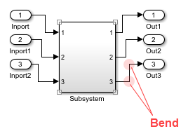
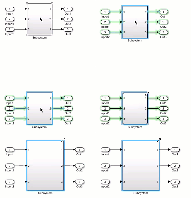
Starting in R2024a, when you move or resize a block with three or more ports, any straight signal lines connecting the block to nearby blocks with one or two ports do not change shape. Instead, the connected blocks move.
If straight signal lines connect the block to a chain of consecutive blocks with one or two ports that are close to each other, the signal lines in the chain do not change their shape. Instead, the blocks move.
The affected signal lines and blocks highlight in green. This new functionality does not affect signal lines with branches or Simscape™ connections.
To temporarily turn the functionality off, hold the space bar while you move or resize a block. When you release the space bar, the functionality turns back on.
To turn the functionality off across MATLAB® sessions, in the Simulink Editor, on the Modeling tab, from
Environment, clear Preserve Alignment.
To turn the functionality back on, select Preserve
Alignment.
Convert Goto and From blocks to signal lines
You can simplify your model diagrams by replacing lengthy signal lines with sets of connected Goto and From blocks. However, when you want to trace a signal path, seeing the signal lines can be useful.
You can convert signal lines and virtual buses to Goto and From block sets, and you can convert Goto and From block sets to signal lines. A Goto and From block set is a connected group of Goto and From blocks that have the same tag.
To convert a Goto block and all From blocks to which it connects or a From block and the Goto block to which it connects to a signal line, select the block. Pause on the ellipsis that appears above the selected block. In the action menu that expands, select Convert to signal.

To convert a signal line or bus to a Goto and From block set, select the signal line or bus. Pause on the ellipsis that appears. In the action menu that expands, select Convert to Goto and From blocks.
For more information about converting between signal lines and blocks, see Convert Signal Lines to Goto and From Block Sets.
Search for and select blocks connected without signal lines using toolstrip button
Related blocks connect to each other without signal lines.
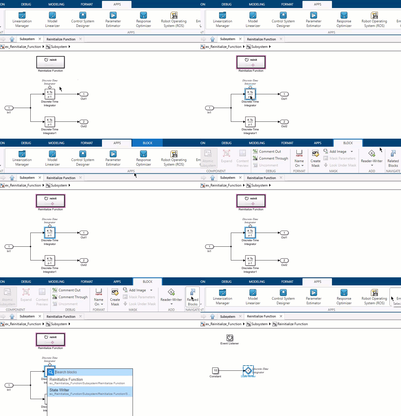
When you select one of a set of related blocks, you can now use the Related Blocks button in the Simulink Toolstrip to find and switch selection to a different block in the set. For example, if you select a Goto block, you can switch the selection to a From block with the same tag. The button both switches selection to the related block and automatically navigates you to the location of the related block.
To switch selection from related block to another, in the toolstrip, on the block-specific tab of the selected block (for example, the Goto tab for a Goto block), in the Navigate section, click Related Blocks.
If the selected block only has one related block, the selection switches to the related block. If the selected block has more than one related block, a list of related blocks appears. Navigate to the name of the block you want to select by clicking or using the arrow keys on your keyboard, then press Enter.
For more information, see Search for Blocks Connected Without Signal Lines.
Enhancements to Model Finder
Model Finder has these enhancements to enable you to search for phrases, customize the Model Finder user interface (UI), and manage databases with ease.
Model Finder now supports using quotation marks for searching phrases to get more targeted results.
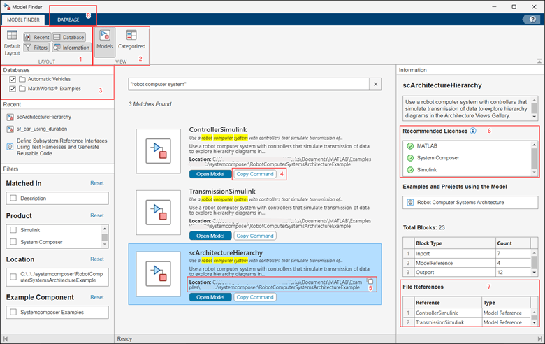
Model Finder UI includes newly added sections and tabs with additional features:
Layout — Customize the UI layout by using buttons to toggle the visibility of the Recent, Databases, Filters, and Information panes.
View — Customize the search results layout using these options:
Models — Select this view to display the models that match your search query. In this view, the search results include both standalone models and models that are referenced by examples and projects. You can view the list of examples and projects that use a specific model in the Information pane.
Categorized — Select this view to display the examples and projects that match your search query. You can view the list of models used in a specific example or project in the Information pane.
Databases — Select the databases from the available list of databases registered with Model Finder to set the search location.
Copy Command — To copy the command that opens a specific search result, click Copy Command.
Location — Display the path on
your system that stores a previously opened search result using the
Model Finder. To copy the path, click the copy icon
.
Recommended Licenses — Display
the licenses recommended to simulate a model, example, or project.
The icons
and
indicate whether you have the
license.
File References — Display the external files that are referenced in the search result.
Database — Manage databases by navigating to the Database tab. Within the tab, you have the option to create, import, delete, and view the contents of a database.
For more information, see Model Finder.
There are some changes in the functions used to configure database settings in Model Finder. For more information, see Model Finder function updates.
View block icons in the quick insert menu
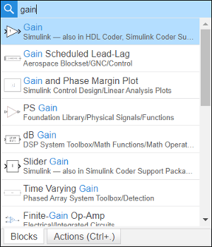
Starting in R2024a, when you double-click the Simulink Editor canvas, the quick insert search results display block icons with the block names to enable you to easily identify the blocks.
Functionality being removed or changed
Model Finder function updates
Errors
Model Finder functions have these changes:
The modelfinder.registerDatabase function is now renamed
to modelfinder.importDatabase.
The modelfinder.unregisterDatabase function is now
renamed to modelfinder.deleteDatabase.
Model Finder no longer supports interactive mode to create, import, delete,
set search, or set default database using the modelfinder.createDatabase, modelfinder.importDatabase, modelfinder.deleteDatabase, modelfinder.setSearchDatabase, and modelfinder.setDefaultDatabase functions.
The functions modelfinder.createDatabase,
modelfinder.importDatabase, and
modelfinder.deleteDatabase no longer accept multiple
input arguments.
Control simulation execution and tune parameter values in scripted simulations
The new Simulation
object represents a simulation of a model and provides an interface to control the
simulation execution and to tune parameter values during simulation. The
Simulation object supports all simulation modes, including rapid
accelerator, and deployment with Simulink
Compiler™. You can use the Simulation object to:
Configure, run, and interact with simulations.
Step forward through major time steps in simulation.
Write and deploy scripts that interact with simulations while they run.
Build and deploy apps that run and interact with simulations.
While you can programmatically interact with simulations you run using
Simulation objects, you cannot interact with the model or simulation
associated with a Simulation object using the Simulink Editor
while the simulation has a status other than inactive.
For more information, see Run Simulations Programmatically.
Interactively build custom apps with Simulink models using MATLAB App Designer
Interactively build a custom app that interfaces with a Simulink model using MATLAB App Designer. Use the App Designer design environment to:
Perform common simulation tasks from the app, such as starting and stopping the simulation and viewing simulation progress, using Simulink UI components.
Tune model variables from the app while the simulation runs by connecting UI components to variables.
Visualize simulation signals in the app by connecting signals to a time scope UI component.
To use Simulink UI components, in App Designer, drag the components from the Simulink section of the Component Library onto the canvas, or use these functions:
uisimdatabutton — Use simulation data buttons to load input data
or save output data.
uisimcontrols — Use simulation controls to start, stop, pause,
and continue a simulation.
uisimprogress — Use a simulation progress bar to view the
simulation progress as it runs.
uisimvartuner — Use a variable tuner component to modify model
variables from a table.
uitimescope — Use a time scope to visualize signal data in the
app while the simulation runs.
For more information, see Create App for Simulink Model.
Debug simulation execution using the Execution Order viewer while stepping block by block
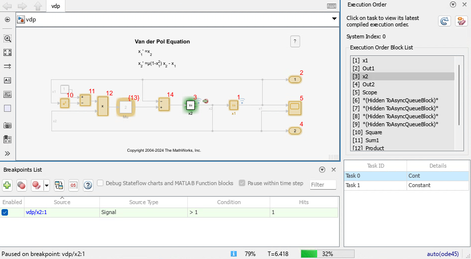
The debugging capability to step through execution block by block that was added in R2023a has improved integration with the Execution Order viewer.
Execution order highlighting no longer conflicts with the block-by-block debugging highlighting that indicates the block on which the simulation is paused.
The Execution Order viewer highlights the row in the execution list that corresponds to the block on which the simulation is paused, so you can track the position in the execution list alongside the location of the block in the model.
The Breakpoints List now has a button to open the Execution Order viewer.
Increased flexibility for stepping block by block in simulation debugging session
When the Pause within time step option is selected in the Breakpoints List and a model contains at least one breakpoint before you start a simulation, you can use the Step Over button to step through the simulation block by block. Starting in R2024a, the Step Over button is available to start stepping block by block anytime such a simulation is paused, including when the simulation is paused between major time steps.
In R2023a and R2023b, the Step Over button was available only while paused within a time step. After the simulation paused within a time step, the Step Over became unavailable if you advanced the simulation through major time steps by using the Step Forward and Step Back buttons. You could not step block by block again until the simulation paused within a time step on a breakpoint.
For more information, see Debug Simulation Using Signal Breakpoints.
Improved support for stepping between Simulink block diagrams and Stateflow charts in simulation debugging sessions
Debugging simulations by stepping block by block in the Simulink Editor has enhanced support for stepping between Simulink block diagrams and Stateflow® charts, including support for these situations:
Stepping into and out of a function-call subsystem that is controlled by a Stateflow chart
Stepping into and out of a Simulink function inside a Stateflow chart
Stepping into and out of a Simulink-based state inside a Stateflow chart
To enable stepping into Stateflow charts in a simulation debugging session, enable the Allow setting breakpoints during simulation configuration parameter before starting the simulation debugging session. For more information, see Breakpoints List.
sldebug prompt in MATLAB Command Window indicates when simulation debugging session is paused within
time step
When you start a simulation debugging session using the Simulink Editor, you
can issue some programmatic simulation debugging commands, such as probe or stop, while the simulation is paused within a time step. The
sldebug command prompt (sldebug >>) now replaces
the MATLAB command prompt (>>) to indicate in the MATLAB Command Window when the simulation is paused within a time step. As in prior
releases, you can issue both MATLAB commands and the supported simulation debugging commands at the
sldebug command prompt.
For more information, see Simulink Debugging Programmatic Interface.
View simulation time in Simulink Editor status bar during programmatic simulations
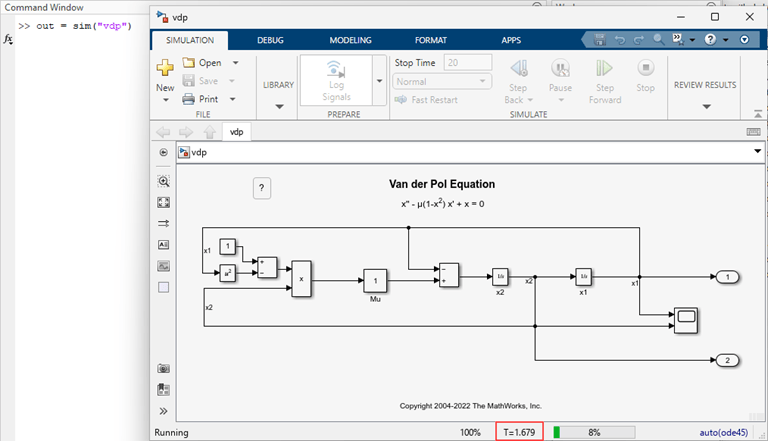
When you run a simulation using the sim function and the model is open, the
status bar at the bottom of the Simulink Editor window for the model now
updates to show the current simulation time for normal and accelerator mode
simulations.
Run fast restart simulations using scalar Simulink.SimulationInput objects
You can now configure a Simulink.SimulationInput object to enable
fast restart for an individual simulation you run using the sim function and a scalar SimulationInput object. Fast
restart saves time in iterative simulation workflows by compiling the model only once, for
the first simulation that has fast restart enabled. When you enable fast restart for an
individual simulation using the sim function, at the end of the
simulation, the FastRestart parameter remains enabled in the model and
the model is initialized in fast restart.
You can also use the setModelParameter function to enable fast
restart by setting the FastRestart parameter on a Simulation
object.
The FastRestart parameter applies for only individual simulations you run one at a time. To use fast restart for multiple simulations you run together using an array of SimulationInput objects, use the UseFastRestart name-value argument.
For more information, see How Fast Restart Improves Iterative Simulations.
Profile execution of iterative simulations using Simulink Profiler and fast restart
Analyze the execution and performance of iterative simulations more quickly by using the Simulink Profiler with fast restart enabled. Fast restart saves time in iterative simulation workflows by compiling the model for the first simulation and then skipping the termination and compilation phases for subsequent simulations. To allow skipping the compilation phase, fast restart restricts the types of modifications you can make to the model. Fast restart is not supported for all models. For more information, see Get Started with Fast Restart.
Enabling and disabling the Simulink Profiler while initialized in fast restart is not supported. To use fast restart with the Simulink Profiler, enable fast restart, and then run a profiling simulation using the Simulink Profiler. After you finish profiling the simulation execution, disable fast restart to terminate the profiling simulation. Disabling fast restart also disables the profiler.
Increased default line width in visualizations
Starting in R2024a, the default line width for signals plotted in the Simulation Data
Inspector, the Record block, the Playback block, and the
Dashboard Scope block is 2 (px).
Improved support for importing MDF-files into the Simulation Data Inspector
The Simulation Data Inspector now offers improved performance and support for importing MDF-files.
Multidimensional data is now imported as a single signal with multidimensional sample values. After importing, you can choose to represent the data as a single signal with nonscalar sample values or expand the signal into a set of signals, called channels, with scalar sample values. Previously, multidimensional data was imported as channels that could not be collapsed into a single signal with multidimensional sample values.
You can now import string data.
Importing large MDF-files into the Simulation Data Inspector is now faster due to improved performance.
Functionality being removed or changed
Code Analyzer warning for sim function syntaxes that return multiple
output arguments
The Code Analyzer
warns about calls to the sim function that return multiple output
arguments. Since R2009b, the single simulation output syntaxes have been recommended, and
multiple output syntaxes have been discouraged.
Support for syntaxes that return multiple output arguments will be removed in a future release.
Consistent error handling for sim function with scalar
SimulationInput object
Behavior change
Starting in R2024a, the sim function has consistent default behavior
and options for simulations you run using Simulink.SimulationInput objects.
In prior releases, the sim function overwrote the
CaptureErrors parameter for a single simulation if you specified one
or more name-value arguments in addition to the scalar SimulationInput
object, including the StopOnError name-value argument.
SimulationInput Dimensions | CaptureErrors | StopOnError | Behavior Change |
|---|---|---|---|
| scalar |
To enable this
parameter, specify the parameter on the | This name-value argument has no effect when you run a single simulation. | Some calls to the |
| vector, matrix, array | Always "on". |
Specify this
name-value argument as | No change. |
slprofreport function has been removed
The slprofreport function and the ability to view profiling data
generated prior to R2020a has been removed in R2024a. In R2020a, the Simulink
Profiler was enhanced to capture profiling data as a Simulink.profiler.Data object to support programmatic analysis of the
profiling results. Since R2020a, the slprofreport function has
supported generating profiler reports only from profiler data generated prior to
R2020a.
Executing size computation phase using model name requires input arguments
Behavior change
In previous releases, typing the name of the model with one or more output arguments and no input arguments executed the size computation phase of simulation. The table describes the behavior for using the model name as a programmatic interface without any input arguments starting in R2024a.
| R2024a Behavior | Code Example |
|---|---|
Typing the model name with one output argument returns the model handle. |
h = MyModel; |
Passing the model name to a function without single or double quotes is equivalent to passing the model handle to the function. |
open_system(MyModel) |
Typing the model name with multiple output arguments and no input arguments causes the software to issue an error. | [sys,x0,blks,st] = MyModel; Too
many output arguments. |
To execute the size computation phase of simulation, you must specify input arguments.
[sys,x0,blks,st] = MyModel([],[],[],"sizes");For more information, see Use Model Name as Programmatic Interface.
Using the model name as a programmatic interface to get a model handle is not recommended.
Instead, after loading the model, use the get_param function to get the Handle parameter for the
model. For example, this get_param command gets the handle for a model
named MyModel.
h = get_param("MyModel","Handle");
Use local solvers for components with faster dynamics
Local solvers for referenced models can now use a fixed step size that is smaller than the step size for the parent solver. Since R2022a, the software has required the local solver step size to be larger than the step size for the parent solver, limiting the use of local solvers to components with slower dynamics compared to the rest of the system. Starting in R2024a, you can use local solvers for components with dynamics that are faster or slower compared to the rest of the system.
Using a local solver can facilitate system composition and integration by:
Allowing system-level simulations to solve referenced models using the same solver and step size that were used to design and test each component in isolation.
Reducing the number of adjustments you need to make to configuration parameters of referenced models when integrating components into larger systems.
For some systems, using a local solver can improve simulation performance by allowing you to:
Choose a solver that is more appropriate to solve the system in the referenced model.
Choose different step sizes for one or more components instead of using a single step size for the entire system, which can reduce the number of redundant calculations in simulations of systems with a wide range of dynamics among components.
For an example, see Improve Simulation Performance by Using Local Solvers.
For more information, see Use Local Solvers in Referenced Models.
Use local solvers for components that contain blocks that wrap state values
Starting in R2024a, you can configure a referenced model that contains a block with wrapped states to use a local solver. Wrapping states can improve numerical stability for systems with cyclical state values and allows the state value to wrap to the start of the cycle without resetting the solver, which can slow simulation performance.
For example, you can model the angular position of a wheel as having a value that is always between 0 and 2π. When the wheel rotates beyond an angular position of 2π, the angular position wraps back to 0 rather than continually increasing.
For more information, see Use Local Solvers in Referenced Models.
Variant Manager for Simulink: Enhanced variant configuration workflow for simulation and testing
Starting in R2024a, models that have variant configurations created using Variant Manager for Simulink have more streamlined simulation and testing workflows. You can now specify variant configurations as inputs to command line functions used to run single or multiple simulations, test cases, or test case iterations on the model. The specified variant configurations are applied before model simulation. This new workflow scales for models with a large number of variant control variables and provides traceability from the result object to the variant configuration used during simulation or testing.
Before R2024a, you had to either set the variant control variables that form a variant
configuration as inputs to the command line functions, or activate the variant configuration
by invoking the Simulink.VariantManager.activateModel function in
callbacks before running the simulation or test.
New command line workflow for simulation and testing:
For simulation functions such as sim,
parsim, and batchsim, you can set the
VariantConfiguration property in the
Simulink.SimulationInput object using the setVariantConfiguration function. For an
example, see Run Simulations for Variant Models Using Variant Configurations.
In the Simulink
Test™ programmatic interface, you can specify the variant configuration to use
when running a test case. You can also run the same test case for different variant
configurations in the model by creating test case iterations. To specify the
configuration that must be activated for each iteration, set the
VariantConfiguration property in the
sltestiteration object. The TestCaseResult and
TestIterationResult objects store the variant configuration used for
each test case or iteration. The test specification report and test results report show
these variant configurations as well. For an example, see Run Tests for Variant Models Using Variant Configurations.
Variant Manager for Simulink: View variant parameters grouped by bank
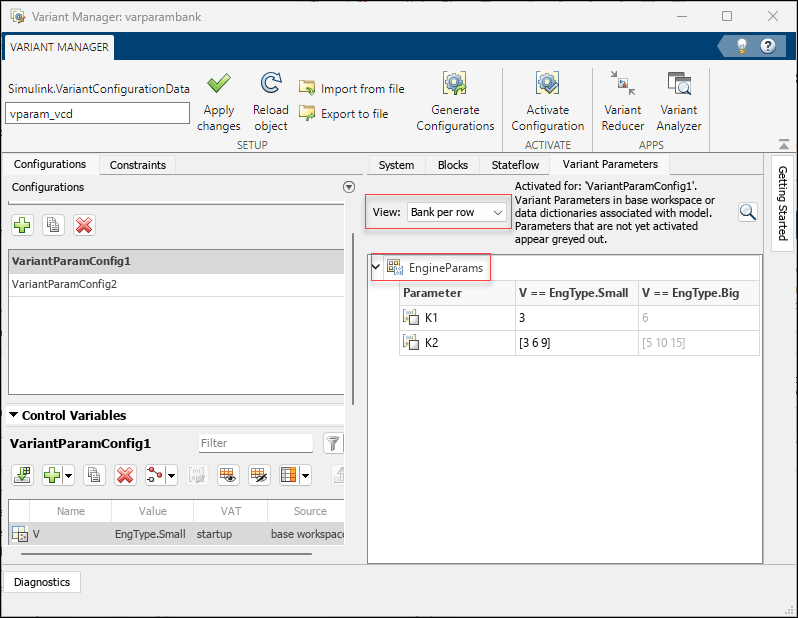
In the Variant Parameters tab in Variant Manager, use the
Bank per row option to switch to a view in which parameters are
grouped based on the variant parameter bank they belong to.
Variant Manager for Simulink: Support for Variant Start and Variant End blocks
Variant Start and Variant End blocks are now supported in Variant Manager tasks such as viewing and interacting with the blocks from the model hierarchy, importing control variables, understanding variable usage in a variant configuration, and activating a variant configuration.
Variant Manager for Simulink: Support for startup variant
activation time in Variant Analyzer
The Variant Analyzer tool supports analyzing variant configurations for a model that
contains variant blocks with startup variant activation
time.
Variant Start and Variant End Blocks: Define conditions in a bounded region without creating a level of hierarchy
Starting in R2024a, use the Variant Start and Variant End blocks to limit variant condition propagation in a bounded region without introducing a level of hierarchy in the model. A bounded region is any region between the outport of a Variant Start block and the corresponding inport of the Variant End block without any intersection. You only need to specify the variant conditions and parameters on the Variant Start block.
Automated port synchronization in Variant Subsystem and Variant Assembly Subsystem blocks
When working with Variant Subsystem or Variant Assembly Subsystem blocks, the ports on the blocks match the ports in their underlying variant choices. In previous releases, you were required to manually analyze, copy, and paste the ports in these blocks to align them with the ports in variant choices, which was a time-consuming and error-prone process. Starting in R2024a, Simulink provides options to add missing ports and delete unused ports in Variant Subsystem and Variant Assembly Subsystem blocks to match the ports of the underlying variant choices. During simulation, if Simulink encounters a port mismatch between a Variant Subsystem or Variant Assembly Subsystem block and its variant choices, the resulting error message now provides these two options to resolve the issue:
Add missing ports — Adds missing ports to the Variant Subsystem or Variant Assembly Subsystem block, aligning them with the ports in the variant choices.
Add and delete ports — Adds missing ports and removes unused ports from the Variant Subsystem or Variant Assembly Subsystem block, aligning them with the ports in the variant choices. The deleted ports cannot be recovered, and any associated properties are lost.
Alternatively, you can use the Simulink.VariantUtils.updateVariantSubsystemPorts function to align the ports
in a Variant Subsystem or Variant Assembly Subsystem block with
the ports in its variant choices.
Use adapted rate-based model blocks as choices in a Variant Subsystem block
Starting in R2024a, you can use adapted rate-based model blocks as variant choices in a Variant Subsystem block. When you add adapted rate-based models as variant choices, the inports in the variant subsystem are matched to the port names of the respective rate-based models.
Define variant control variables of a Simulink Function block in the mask or model workspace
Starting in R2024a, you can define the variant control variables of a Simulink
Function block with update diagram activation time in the mask
or model workspace.
Access the mask of the active variant choice on Variant Subsystem block
Starting in R2024a, you can access the mask of the active variant choice of the Variant Subsystem directly without having to navigate inside the Variant Subsystem block with the following conditions:
If the Variant Subsystem block is unmasked, double-clicking on the block opens the mask of its active choice. Clicking on the Look under mask badge or selecting the corresponding option from the context menu of the Variant Subsystem block takes you directly inside the active choice.
If the Variant Subsystem block is masked and the active choice also has a mask, then the mask of the Variant Subsystem block gets the preference and double-clicking on the block will open the Variant Subsystem block mask.
Specify variant choices as an array of strings in Variant Assembly Subsystem block
Starting in R2024a, you can specify Variant choices specifier as an array of strings in Variant Assembly Subsystem block.
Propagate variant conditions to elements connected to the inport bus of the Bus Creator block in variant models with busses
Starting in R2024a, the variant conditions propagate to the elements connected to the inport bus of the Bus Creator block. Additionally, the generated code is optimized to execute based on the selected variant, eliminating any unnecessary code execution for inactive variants. Previously, in variant models that included buses, the elements connected to the inport bus of the Bus Creator block would always be active, regardless of the selected variant.
Specify custom header files without #include directive
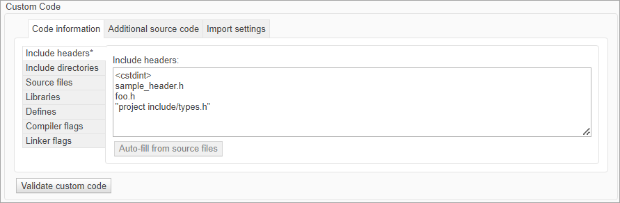
Starting in R2024a, the Include headers parameter in
Simulation Target and Code Generation tabs
support a list of custom header files without #include directive. For
more information, see Include headers.
Simulink Code Importer: Import C++ Class as reusable Simulink library
Starting in R2024a, you can use the Simulink Code Importer to import a C++ class to a Simulink Library from your custom C++ code library. For example, using the Simulink Code Importer you can import C++ class to a C Function block after analyzing the custom code for classes and their dependencies. For more information, see Import Custom C++ Class Using the Simulink Code Importer Wizard.
New example of modeling a Battery Management System
A new example shows how to design, model, and simulate a Battery Management System (BMS) for an NMC (Nickel-Manganese-Cobalt) cell with 3 Amp hr capacity. This example will include the best practices for collaboration, model composition and components, and interface and data management. For more information, see Use Model-Based Design To Build a Battery Management System.
Convert logically executed Subsystem blocks to Subsystem Reference Blocks to reuse in models
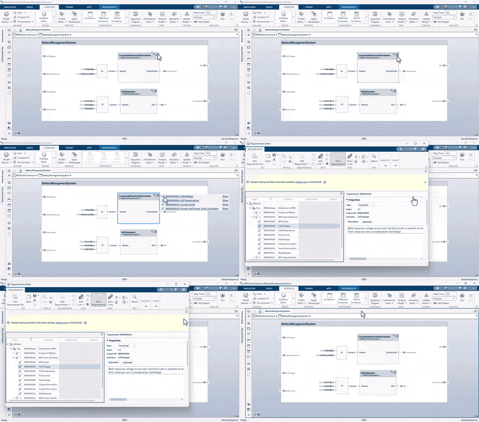
You can now convert logically executed Subsystem blocks such as If Action Subsystem, Switch Case Action Subsystem, For Iterator Subsystem, and While Iterator Subsystem to Subsystem Reference and reference them in models to promote reusability and modularity. For information on converting Subsystem blocks to Subsystem Reference blocks, see Convert Subsystem to a Referenced Subsystem.
Optimized loading of models with Variant Assembly Subsystem blocks
Starting in R2024a, when you load a model with a Variant Assembly Subsystem block that has variant choices stored in subsystem files, only the active choice is loaded. This optimization shortens the loading time for such models.
Share port constraints with other masked blocks
Starting in R2024a, you can create shared port constraints enabling you to reuse them with other masked blocks. By saving the port constraints separately in an XML file, you can easily apply them to multiple masked blocks to achieve consistency and efficiency.
For more information on sharing a port constraint, see Share Port Constraints Across Multiple Masked Blocks.
Use constraints on literal edit parameters
You can associate constraints to literal edit parameters. If the Evaluate option in the Mask Editor is not selected, Simulink takes a literal reading of the input entry as you type it in the mask parameter dialog box. For example, you can store an IP address including the dots in a literal edit parameter. Simulink does not evaluate the parameter as if it were a mathematical expression. For more information, see Custom Constraint for Mask Parameter.
Optimized execution of mask parameter callback
Starting in R2024a, mask callback parameter does not execute if the parameter value remains unchanged. This improves the efficiency of mask callbacks by preventing unnecessary execution when the parameter value remains the same.
Functionality being removed or changed
Extraneous discrete derivative signals diagnostic has been removed
Errors
The Extraneous discrete derivative signals
(ModelReferenceExtraNoncontSigs) diagnostic configuration parameter
has been removed.
When a discrete input to a Model block connects to the input of a block that has continuous states, the software resets the solver each time the discrete signal updates. The software does not issue a warning or error. Previously, the default behavior of this diagnostic was for the software to issue an error.
To diagnose solver resets, use the Solver Profiler instead. The Solver Profiler provides the number of resets and the reset sources. For more information, see Solver Resets.
Invalid root Inport/Outport block connection diagnostic has been removed
Errors
The Invalid root Inport/Outport block
connection (ModelReferenceIOMsg) diagnostic
configuration parameter has been removed.
When internal connections to the root-level port blocks of a model are invalid, the software silently inserts hidden blocks to satisfy the constraints wherever possible. This behavior matches the previous default behavior.
To diagnose and fix invalid connections, use Model Advisor check Check for invalid root input and output port connections (Simulink Check) (ID:
mathworks.hism.hisl_0079) instead.
Reference tunable mask enumeration parameter by its name in child blocks to obtain the custom value associated with the option
Behavior change
If a mask enumeration parameter refers an external enumeration file or enumeration class for its options, you can now reference the parameter by its name in child blocks to obtain the custom value associated with the option during simulation and code generation.
Previously, child blocks had to reference tunable mask enumeration parameters using an
internally created value array that contained the option values. The parameter name was
referred to as valueArrayName(<parameterName>) to obtain the custom
value for an option. For more information, see Tune Mask Enumeration Parameters - Popup and Radio Button.
lcc-win64 compiler not supported
Errors
The lcc-win64 compiler is no longer supported. For information about supported compilers, see Supported and Compatible Compilers - Windows.
Simulink.VariantControl object does not support Simulink.Parameter object with slexpr or nonscalar values
Behavior change
Starting in R2024a, the Simulink.VariantControl object does not support setting its
Value property to a Simulink.Parameter object with Value set to the slexpr
function or a nonscalar value.
Project API: Find project files by label
You can now programmatically perform an advanced search in a project using the
findFiles function. Supported workflows include:
Listing all files in a project
Filtering files that are not part of the project
Finding files by label or category name
Creating test suites from test files in a project and its references
Project API: Reanalyze all project dependencies
You can now programmatically reanalyze all files in your project and perform a
complete dependency analysis by using the updateDependencies function.
Project API: Export list of project files to archive
You can now programmatically export a list of project files to an archive by using the
export
function.
For projects that have missing files, you can enable the export
function to ignore the missing files.
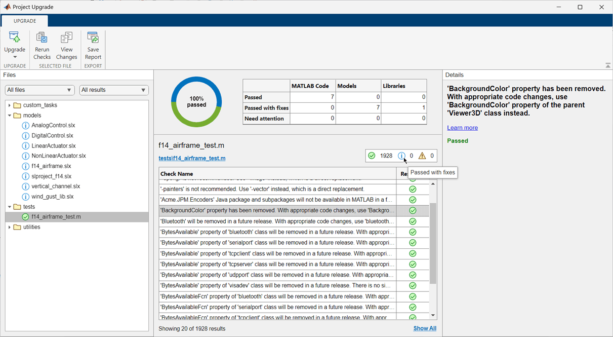
Project Upgrade: Check for compatibility issues and upgrade project with improved usability and appearance
For projects that contain only MATLAB files, use Project Upgrade to check for compatibility issues with the current release. For projects that also contain Simulink models and libraries, you can apply fixes and automatically upgrade your project to the current release.
You can now easily interpret the upgrade results and examine the checks marked as need attention. You can also access frequent actions from the Project Upgrade toolstrip:
Rerun checks.
View changes that the upgrade applied.
Save results in a report.
For more information, see Check for Compatibility Issues and Upgrade Simulink Models Using Project Upgrade.
Source Control: Support for signing Git commits
You can now enable the MATLAB Git™ integration to sign Git commits automatically. For more information, see Enable Signing Commits.
Source Control: Support for Git hooks
MATLAB Git integration can now run Git hooks with no additional setup. Starting in R2024a, you do not need to install Cygwin™ on Windows®.
Supported hooks are pre-commit, commit-msg,
post-commit, prepare-commit-msg,
pre-push, pre-merge-commit,
post-checkout, and post-merge. For more
information, see Set Up Git Source Control.
Source Control API: Discard changes in Git repositories programmatically
You can now programmatically restore modified files in a Git repository using the discardChanges function.
Dependency Analysis API: Analyze Files in Toolbox and Files with Unsaved Changes
You can now programmatically include files inside of a toolbox and files with unsaved
changes in your dependency analysis using the dependencies.fileDependencyAnalysis function.
Source Control in MATLAB Online: Expanded support for Git workflows
MATLAB Online™ now provides expanded support for Git workflows:
Squashing Git commits
Rebasing Git branches
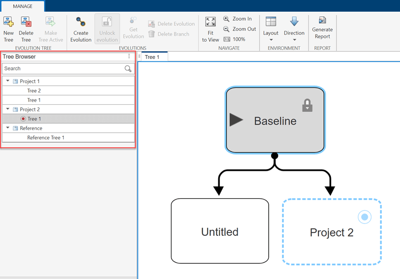
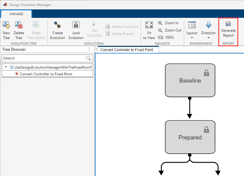
Design Evolution Manager in MATLAB Online: Quickly browse, view, and switch between evolution trees
polyspaceArtifact Function: Generate artifacts necessary for Polyspace analysis without regenerating code
In R2024a, you can generate Polyspace® artifacts for a Simulink model without regenerating the code by calling the function
polyspaceArtifact. You do not need to integrate Polyspace with Simulink to use this function. The function polyspaceArtifact is
available with Simulink R2024a. This function generates two artifacts:
Data range specifications — The data ranges of the generated code summarized in an XML file.
Link-to-model data — The data to link the generated code to the Simulink model summarized in an XML file.
This function generates individual XML files. Access to individual Polyspace artifacts outside of an archive can be useful in a continuous integration workflow.
Some changes in your model might require updating these artifacts without requiring
updates to the generated code. For examples, If you change the Minimum or
Maximum attribute of a signal in your model, only the data range
specification needs to be updated to run a more precise Polyspace analysis. Use polyspaceArtifact function to generate the
new data range specification XML file quickly without requiring a complete regeneration of
your code.
For more details about the function, see polyspaceArtifact.
Functionality being removed or changed
dependencies.fileDependencyAnalysis(modelname,manifestfile)
syntax will be removed
Warns
The dependencies.fileDependencyAnalysis(modelname,manifestfile)
syntax of the dependencies.fileDependencyAnalysis function will be removed in a
future release. Use the dependencies.fileDependencyAnalysis(modelname,
ManifestFile="manifestFileName") syntax instead. Starting in R2024a,
scripts using
dependencies.fileDependencyAnalysis(modelname,manifestfile)
warn.
Programmatically interact with workspaces and data dictionaries using a common interface
You can now use a common command-line interface to programmatically interact with the base
workspace, model workspace, and the Design Data section of a data dictionary. Create
a data connection object to any of these types of data sources by using the
Simulink.data.connect function. Then use the object to
interact with your design data.
Read variables by using dot notation (for example val =
ds.x).
Assign variables by using dot notation (for example ds.x =
val).
Read and assign multiple variables by using the get
and set object functions.
Work with data sources by using object functions that are similar to
functions you use when working with the base workspace (such as
who, exists, and
clear).
Manage changes to data sources by using the
hasUnsavedChanges,
saveChanges, and
discardChanges object functions.
Open the data source in Model Explorer by using the
show object function.
Get the metadata available for a specific variable by using the
getMetadata object function.
By default, tab completion for the data connection object includes only functions
available to the object. The Simulink.data.connect function
provides the option to configure tab-completion to include only object functions,
only variables, or both functions and variables.
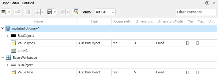
Type Editor: Manage types across multiple external data sources associated with your model
When the Type Editor is docked in a model window, the Type Editor displays the available types for the model grouped by source. Create, edit, and assign types stored in the base workspace or data dictionaries.
For more information, see Type Editor.
Create Simulink.Bus objects from bus element port
specifications
To create Simulink.Bus objects from buses at bus element ports, use the
Simulink.Bus.createObject
function.
Signal Editor tool updates
The Signal Editor tool has these updates:
The Signal Editor tool Move button
has been removed. The move action is now combined
with the select action. You can select and move one point, two contiguous points on the
same line, or the entire plot. In releases prior to R2024a, the
Move button enabled you to move only the entire plot. For
more information, see Move Signal Points in Signal Editor.
Change plot x- and y-axes limits in the SignalX.Scenario Axes Properties panes. When you change the limit, the plot adjusts your view. For an example, see Change x- and y-axes limits.
To synchronize all the signals in open plots by time (x-axis), select Synchronize X-limits in the Synchronize.SignalX Axes Properties pane. Use this setting to also synchronize zooming, panning, and fit-to-plot. For an example, see Add and Edit Multidimensional Signals.
Signals in the plot or data table are now linked. Selecting a point in the plot highlights the associated data in the table. Vice versa, selecting a data point in the table highlights the associated point in the plot. Deleting a point in the plot deletes the associated data in the table. Vice versa, deleting a data point in the table deletes the associated point in the plot. For an example, see Add and Edit Multidimensional Signals.
Move signal points in Create Signal live task
The Create Signal
Move button
has been replaced by the Select and Move
point(s) button
. The move action is now combined with the select action.
This button enables you to select and move one signal point, two contiguous signal points on
the same line, or the entire plot. In releases prior to R2024a, the
Move button enabled you to move only the entire plot. For more
information, see Create
Signal.
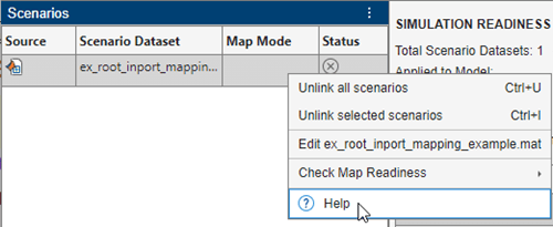
Access context-sensitive help in Root Inport Mapper
The Root Inport Mapper tool has added access points for context-sensitive help:
In the Scenarios pane title bar, click the context menu icon.

Right-click a row of the Scenarios pane.
fixdt supports C/C++ code generation
The fixdt function now supports C/C++ code
generation.
New configuration parameters for finer control of parameter overflow and precision loss diagnostics
Simulink has new configuration parameters that give you finer control over filtering of parameter overflow and precision loss diagnostics.
Access these new parameters in the Diagnostics > Data Validity pane of the Configuration Parameters dialog box:
Bits of error threshold — Set a threshold of one bit, half bit, or zero bits for parameter overflow detection.
Suppress double to single detection — Suppress the double to single parameter precision loss detection.
Absolute difference threshold — Report parameter precision loss when the quantization error exceeds both absolute and relative difference thresholds.
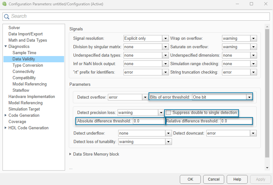
Relative difference threshold — Report parameter precision loss when the quantization error exceeds both absolute and relative difference thresholds.
Parameter Quantization Advisor: Toolstrip-based UI
The Parameter Quantization Advisor interface now includes a simplified toolstrip with new features.
Filter data:
Use the Overflow, Underflow, and Precision Loss filters to show or hide diagnostic data.
Use the Parameters Without Diagnostics filter to show or hide issues that are lossless and quantization issues that are filtered out due to Configuration Parameter settings.
Open the Configuration Parameters dialog box directly from the app using the Model Settings button.
Refresh data in the app using the Refresh Data button.
Diagnostics that are suppressed with Simulink.SuppressedDiagnostic are
now automatically hidden in the app. You can use the Parameters
Without Diagnostics filter to display these diagnostics in the
app.
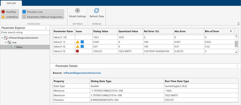
Parameter Quantization Advisor: Support for structures, bus, and
Simulink.Parameter objects
The Parameter Quantization
Advisor now supports structures, bus objects, and
Simulink.Parameter objects.
To open the app for a Simulink.Parameter object, at the MATLAB command prompt, enter this
command.
parameterQuantizationAdvisor('model name','Simulink.Parameter object name')
To open the app for a parameter with a structure value, at the MATLAB command prompt, enter this command.
parameterQuantizationAdvisor('block path','parameter name')
Use symbolic expressions for string data types
Starting in R2024a, you can use symbolic expressions for the maximum length of string data types for a subset of Simulink blocks. Symbolic expressions allow you to:
Update the maximum length simply by updating the corresponding symbolic expression values.
Avoid rebuilding the model each time you need to update the maximum length.
For more information on creating string data types, see stringtype.
Functionality being removed or changed
Error reported when you load MPT objects last created or modified before R2012b
Behavior change
In R2024a, if you load a .mat file or a .slx file
that contains mpt.Signal or mpt.Parameter objects that
were last created or modified before R2012b, Simulink reports one of these error messages:
Class .mpt.CustomRTWInfoSignal not supported in R2024a and removed in R2024b. Migrate instances of this class to the new supported class
Class .mpt.CustomRTWInfoParameter not supported in R2024a and removed in R2024b. Migrate instances of this class to the new supported class
To resolve this error, load the .mat file or .slx file in a release later than R2012a and before R2024a. Then resave the file.
Dock dashboard panels
You can now dock dashboard panels to the Simulink Editor window. You can use the docked panel to monitor signals and control parameters during simulation without covering the model diagram in the canvas.
To dock a panel, select the panel. If the panel has multiple tabs, select any tab. Then,
pause on the ellipsis (…) that appears. In the action menu that expands, click the Dock
button
.
To return the docked panel to the canvas, click the Open in canvas button
.
For more information, see Dock Panels.
Use Expand Scalar block to create scalar expanded matrices
To create scalar expanded matrices, use the new Expand Scalar block.
New Array Processing Subsystem block
Use the new Array Processing
Subsystem block to apply an algorithm to each element of a matrix, similarly to
the arrayfun function. Use Array
Processing Subsystem blocks to efficiently process large input matrices such as
image and video data.
New Pixel Processing Subsystem block
Use the new Pixel Processing Subsystem block to apply an algorithm to each pixel in multichannel image data and derive a single-channel output image. The Pixel Processing Subsystem block processes n-dimensional input data like a Neighborhood Processing Subsystem block that has a 1-by-1-by-n neighborhood size.
For an example of how to use the Pixel Processing Subsystem block, see Convert RGB Image to Grayscale by Using a Pixel Processing Subsystem Block.
MinMax block supports specified dimensions
The MinMax block now enables you to find minimum or maximum values over a specified dimension using these new parameters:
Apply over — Apply function over all or specified dimensions.
Dimension — Dimension over which to apply the function.
Sum, Sum of Elements, Subtract, Add, Product, Matrix Multiply, and Product of Elements blocks have new parameter names
These parameters for the Add, Sum, Sum of Elements, Subtract, Product of Elements, and Product, Matrix Multiply blocks have been renamed.
| Block | New Parameter Name | Old Parameter Name |
|---|---|---|
| Sum, Sum of Elements, Subtract, Add | Apply over | Sum over |
| Product, Matrix Multiply, Product of Elements | Apply over | Multiply over |
Width block supports symbolic dimensions
The Width block has these changes:
Support for symbolic dimensions.
New parameter, Always use constant sample time.
Data store blocks support indexing for symbolic dimensions
The Data Store Read and Data Store Write blocks now support indexing when the Data Store Memory block uses symbolic dimensions.
From Spreadsheet block supports relative and full paths for File name
The From Spreadsheet block now supports relative and full paths for File name for simulation and code generation. In releases prior to R2024a, if you specified a relative path for File name, the From Spreadsheet block changed the relative path to the full path during code generation.
Support for variable-size input signals in Discrete Filter and Discrete Transfer Fcn blocks
The Discrete Filter and the Discrete Transfer Fcn blocks support variable-size input signals when you set the Input processing parameter to Columns as channels (frame based).
When the input is a variable-size signal, you can change the frame size (number of rows) of the signal during simulation but the number of channels (columns) must remain constant.
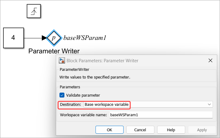
Write to base workspace variable or variable in data dictionary using Parameter Writer block
Starting in R2024a, you can use a Parameter
Writer block to write to a base workspace variable or a variable that you create
in Simulink.data.Dictionary. To configure a
Parameter Writer block to write to such a variable, in the Block
Parameters dialog box:
Select Base workspace variable from
Destination parameter options.
Enter the variable name in Workspace variable name field.
Before R2024a, you could only write to a model workspace variable or a block parameter using Parameter Writer block. The new parameter, Destination replaces the existing Access model workspace variable parameter.
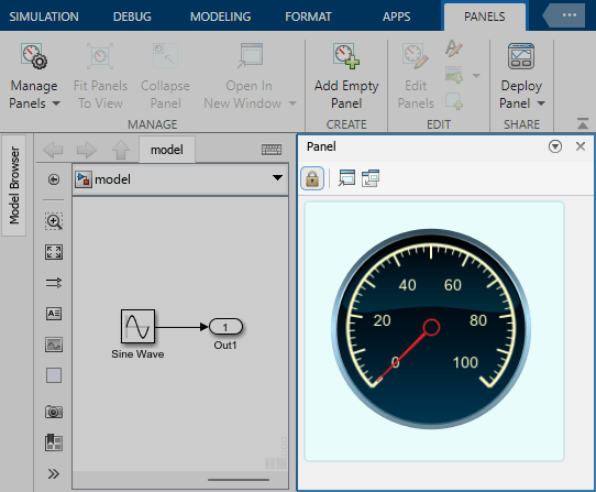
Monitor signal values during simulation using customizable Half Gauge and Quarter Gauge blocks
To monitor signal values during simulation, you can now use Half Gauge and Quarter Gauge blocks that can be customized to look like gauges in real systems. The new blocks are located in the Customizable blocks library. The blocks are functionally the same as the Circular Gauge block but are visually pre-configured to look like gauges shaped as a half- and quarter-circle, respectively.

Display block from Customizable Blocks library can display strings
The Display block from the Customizable Blocks library can now connect to and display signals that are strings.
Deploy dashboard panel as web app or standalone desktop app
With a Simulink Compiler license, you can now deploy a dashboard panel, packaged with the model to which the panel connects, as a standalone desktop app or as a web app. You can use the app to operate the controls and monitor the displays on the panel independent of Simulink.
To learn how to deploy panels, see Deploy Dashboard Panel as App.
Dashboard panels support Windows display scaling of over 100%
Dashboard panels support Microsoft®
Windows display scaling values higher than 100%.
Programmatically add data to the Playback block
The Playback block now has a Signals parameter that you
can use to retrieve information about signals in the block or add new signals to the block
using the get_param and set_param functions.
For example, to add signals from the workspace to the Playback block programmatically:
Use the Simulink.playback.createSignals function to
create a Simulink.playback.Signal object for the signals you
want to add to the Playback block. Specify the source of the data
as the workspace, and list the variable names of the signals to be added.
Use the set_param function to set the
Simulink.playback.Signals object as the value of the
Signals parameter.
pbSig = Simulink.playback.createSignals("workspace","Variables",["x1","x2"]); set_param("PlaybackModel/Playback","Signals",pbSig);
For more information, see Simulink.playback.Signal and Simulink.playback.createSignals.
Search for signals to add to the Playback block
When you use the Add Signals dialog box to add signals to the Playback block, you can now search for specific signals. As you type the signal name, the table of signals updates to display only the signal names that contain your search term. You can also refine your search to exclude partial matches, match specific capitalization, or use regular expressions to find signals that follow a certain pattern.
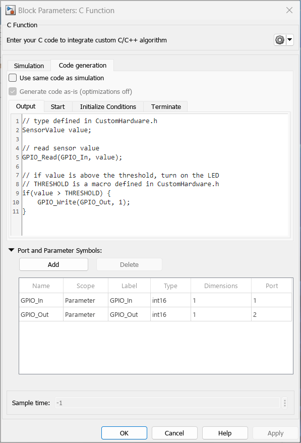
Support for target-specific code generation for C Function block
Starting in R2024a:
You can specify target-specific code for code generation interactively using
the Code generation tab in the C
Function Block Parameters dialog box. Before R2024a, you could
specify the code only programmatically by using #ifndef
MATLAB_MEX_FILE.
The target-specific code you specify does not need to be compatible with desktop MEX compilers.
You can embed the target-specific code in the model-generated code without optimizations.
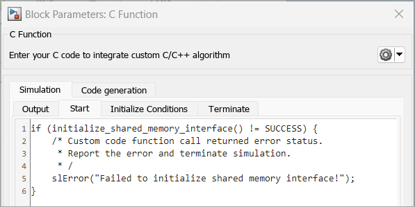
Report error and warning messages in C/C++ code in C Function block
Starting in R2024a, you can report run-time errors and warnings in C/C++ code that you
write in a C Function
block. Use slError and slWarning to report
run-time errors and warnings, respectively. Error messages indicate unexpected conditions in
the code, and warning messages flag potential issues in the code. An error message
terminates the simulation. If you see a warning message, you can either terminate or
continue with the simulation. For more information, see Report Run-time Errors and Warnings in Simulink.
You can view the error and warning messages using the Diagnostic Viewer in the Simulink canvas.
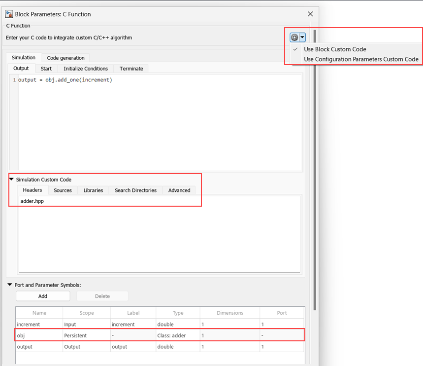
Specify custom code in C Function block
Starting in R2024a, you can specify your custom C code locally in a C Function
block. For multiple C Function blocks, this change allows you to specify only
the dependencies associated with the custom code for a specific C Function
block. In the Block Parameters dialog box, click the down arrow next to
icon and select Use Block Custom
Code option.
Before R2024a, you could specify the code only globally using model configuration parameters.
Specify row-major and column-major arrays in custom code for C Function block
Starting in R2024a, you can specify row-major and column-major arrays by using the
slSetRowMajor and slSetColumnMajor functions
in the C Function block custom code. For more information, see Specify Row-Major and Column-Major Array Layouts in Custom Code.
Out Bus Element block: Specify additional elements and their attributes without adding blocks or bus objects
When a subsystem or model has an output bus element port, you do not need to specify a
Simulink.Bus object or add Out Bus Element blocks
to:
Add elements to the output port.
Specify attributes of the elements at the output port.
For more information, see Define Output Bus Without Extra Blocks or Bus Objects.
To programmatically add elements to the output bus without adding blocks to the block
diagram, use the Simulink.Bus.addElementToPort function.
Bus element ports and function ports have more intuitive block interactions
When you interact with In Bus Element, Out Bus Element, Function Element Call, and Function Element blocks, the results of your actions are more consistent and clear.
When you press Ctrl and drag the blocks to a new position, you receive these options:
New Port — Create a port.
New Element — Add an element to the port. Out Bus Element and Function Element blocks support this option only when the dragged block represents an element of the port and not the full port.
Duplicate — Create a duplicate In Bus Element or Function Element Call block. Out Bus Element and Function Element blocks do not support duplication.
These actions consistently create a port:
Double-click the canvas. In the Quick Insert menu, start typing the name of one of the blocks. Then, select the block from the menu.
Copy and paste one of the blocks.
For more information about these blocks, see In Bus Element, Out Bus Element, Function Element Call, and Function Element.
Bus Selector block: Right-click elements in dialog box to access options
In the Block Parameters dialog box of a Bus Selector block, right-click elements and select the desired action.
Add to output — Add elements from the input bus to the block output.
Highlight source blocks — Highlight the source blocks of elements in the input bus.
Remove — Remove elements from the block output.
Remove all invalid elements — Remove all output elements that are not in the input bus. The invalid element names are red.
For more information, see Bus Selector.
Bus Selector blocks have more intuitive parameter names and interactions
When you interact with Bus Selector blocks, the results of your actions are more clear.
The Select elements button
is now the Add to output button
.
The Selected elements list is now the Output elements list.
The Output as virtual bus button
is now the Output as virtual
bus check box.
For more information, see Bus Selector.
Graphical Icon Editor: Reuse common icon elements using base part
Starting in R2024a, you can designate a part of a block icon as the base part, allowing all other parts of the icon to inherit its elements. Designating a base part has these advantages.
There is no need to duplicate common elements in each part, resulting in a lighter icon file.
Managing the icon is easier since any changes made to the base part of the icon propagate to all other parts of the icon.
For more information on pinning a part as a base part, see Render Multiple Variations of Same Block Icon Using Parts
Graphical Icon Editor: Evaluated mask workspace variables are supported as icon data
Starting in R2024a, you can access evaluated workspace variables as icon data. You can use these values to set conditional visibility, layout constraints, or text parameterization. Additionally, you can retrieve the integer values of enumerations assigned to the workspace variables.
The syntax to access the evaluated value of a mask workspace variable is:
value@maskWorkspaceVariable ===
value
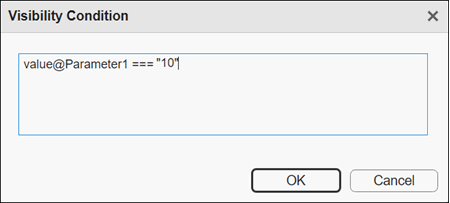
For example, set the visibility condition for an icon element.
value@Parameter1 === "10"
The syntax to access the evaluated value of an enumeration member is:
value@enumerationMember ===
"enumerationValue"
For example: Set the condition visibility for an icon element based on the evaluated value of the enumeration member.
value@open_orifices_pos === '2'
Previously, the condition was set as
open_orifices_pos ===
'fluids.thermal_liquid.valves.directional_control_valves.enum.OpenOrifices3Way.PA'
For more information on evaluated parameters, see Set Visibility Condition Based on Evaluated Value of Parameters
Note
The supported datatypes for the resolved parameter are numeric, boolean, and string.
Graphical Icon Editor: Adapt block icon color to Simulink canvas color
Prior to R2024a, the block icon's default color was white, regardless of the canvas color. However, starting from R2024a, you now have the option to make the background of the block icon transparent, allowing the Simulink canvas color to show through. You can also set, the background color of closed shape elements inside the block to inherit the Simulink canvas color. For more information, see the icon properties pane table in Edit Properties of Block Mask Icon and Its Elements.
Graphical Icon Editor: Repeat icon elements on multiple ports
Starting in R2024a, you can use the Repeat Parameterization option to repeat icon elements on multiple ports of a block. You can choose to repeat the elements based on the position of the ports.
For example, you can repeat an icon element for all the left ports of the block and left align the elements of the block.
To repeat an icon element, right-click the element and select Parameterize from the context menu. In the Element Parameterization panel, select the position of the ports and the alignment of the elements for each port.
For more information on repeating icon elements, see Repeat Icon Elements on Multiple Ports.
Graphical Icon Editor: Preview variations of a block icon
Starting in R2024a, you can preview variations of a block icon based on visibility conditions and parameters using the options Parameter Variations and Width Height Variations. These options are available along with other preview options in Simulink canvas. For more information, see Design Complex Block Icon Using Parts and Preview the Variations
Specify height, width, and alignment for an image in a block icon
You can now specify image alignment details by using mask icon drawing commands, including alignment to the left, right, top, and bottom margins. You can also specify the width and height of the image as a percentage of the width and height of the block. For more information, see image.
For example:
image("path\to\image",[leftMargin, topMargin, rightMargin,
bottomMargin, widthPercentage, heightPercentage])
image("airplane.jpg",[0,0,10,10,90,90])

Add parameters from base class in system object masks
Starting in R2024a, the Base Class Property parameter in a system object mask allows you to access available parameters from the system object file and modify the mask by adding parameters inherited from the base class. You can add or remove parameters from the base class, but it is not possible to remove parameters from the derived class. This ensures that the necessary parameters and functionality from the derived class are retained in the mask.
For more information, see Create and Customize MATLAB System Icon and Dialog Box Using Mask Editor.
PID Controller Blocks: Use derivative signal from external source
The PID controller blocks now allow you to supply the derivative of the plant signal y directly as an input to the block. This is helpful when you have the derivative signal available in your model and want to skip the computation of the derivative inside the block.
To enable the input port for supplying the derivative, select a controller type that has derivative action and enable the Use externally sourced derivative parameter.
Report runtime diagnostics for MATLAB System block in rapid accelerator mode
Report runtime errors for MATLAB System blocks when simulating in rapid accelerator mode by using one of these options:
Open the Configuration Parameters window. In the Modeling
tab, click Model Settings. In the Configuration Parameters
window, click Simulation Target, expand
Advanced Parameters, and set the Enable memory integrity checks
configuration parameter to Always on.
Use the set_param function to set the
SimIntegrity parameter to 'alwaysOn'. For
example, to enable diagnostics for a model named model_name, enter
this
command:
set_param('model_name','SimIntegrity','alwaysOn');
Simulate FMU without defining bus objects or enumeration classes
You can now simulate an FMU that contains ports with bus or enumeration data types without
having to manually define a bus object or enumeration class in the current Simulink session. The FMU
block uses the metadata inside the modelDescription.xml file to determine
the signal attributes for bus and enumeration type ports. This enables downstream and
upstream blocks to inherit enumeration data type and downstream blocks to inherit bus data
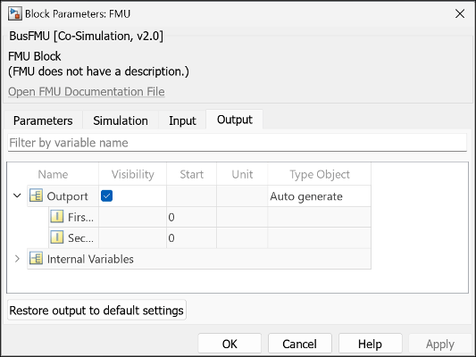
types. To enable direct simulation and propagation, open the FMU dialog box and set
Type Object attribute to Inherit:auto
for input and output ports with enumeration data types and Auto
generate for output ports with bus data types.
Generate binary for FMU from source code
You can now generate binaries of FMUs on the corresponding platforms from its source code
using the fmudialog.compileFMUSources function. For example, you can
use this function to generate the Linux® binary for an FMU that includes the source code but does not include the
binary required for simulation on Linux platform.
Improve simulation performance of Python functions integrated into Simulink using Python Importer
Starting in R2024a, the simulation performance of the blocks generated by Python® Importer, which integrates Python functions into Simulink, is improved by generating C-wrappers that are used to call the specified Python functions. This enhances the simulation performance of the blocks, enables simulation in rapid accelerator mode, and supports simulation in model reference with accelerator mode. You will need to have Python installed in your system to perform the simulation.
This enhancement is not supported for Python functions that are defined inside classes.
Launch external debugger from Simulink for debugging FMU
You can now directly launch an external debugger for debugging FMU from Simulink without manually configuring the external debugger to connect to Simulink.
Use the fmudialog.compileFMUSources function with
'DebugMode' argument set to 'on' to generate
debugging information for an FMU that contains its source code.
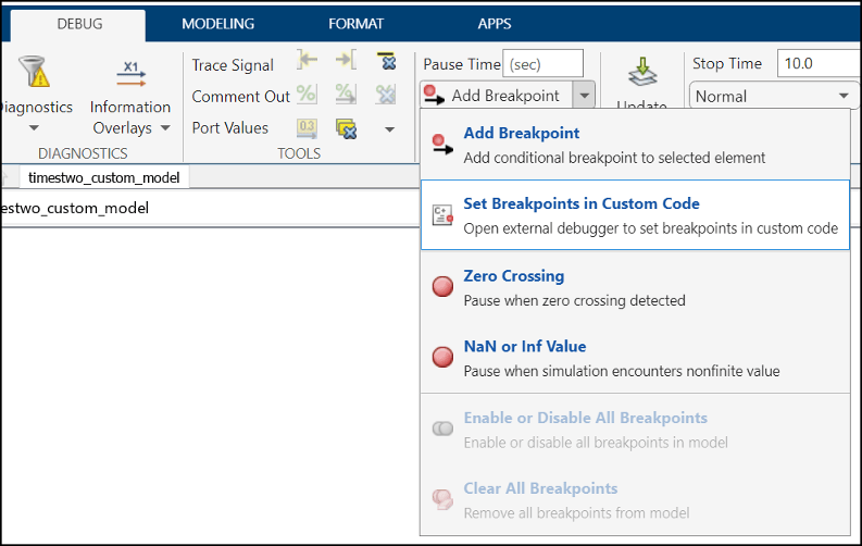
To launch the external debugger, go to the Debug tab in Simulink and select Set Breakpoints in Custom Code option.
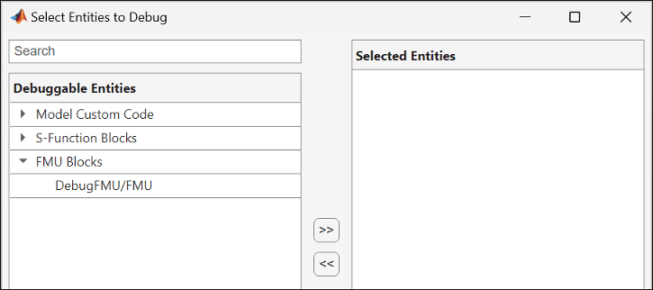
The Select Entities to Debug dialog box lists the entities that can be debugged. The FMUs that can be debugged are listed under FMU Blocks. Select the FMU that you want to debug and move them to Selected Entities.
Click Open to launch the external debugger.
Assign units to ports and parameters in S-Function Builder
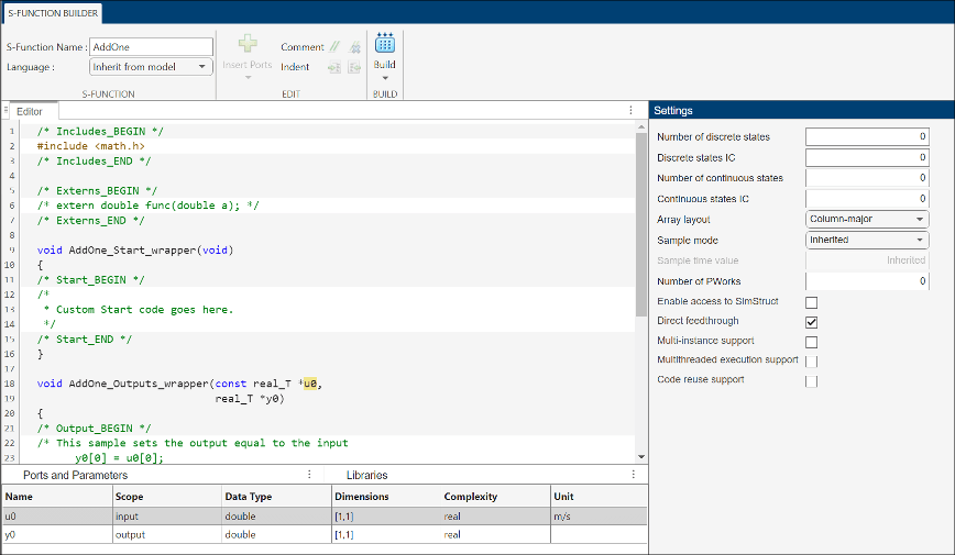
Starting in R2024a, you can assign units to ports and parameters in S-Function Builder.
Use the Simulink.SFunctionBuilder.update function to assign units to ports or
parameters. For example, the following code assigns m/s as the unit for
the first input of s-function AddOne.
Simulink.SFunctionBuilder.update('AddOne','Input','u0','Unit','m/s');
You can also specify units in the Units column of Ports and Parameters table in the S-Function Builder.
Enhancements to FMU block importing FMU compatible with FMI 3.0 standards
FMU block importing an FMU that is compatible with FMI 3.0 standards has the following enhancements. Starting in R2024a you can:
Generate code for model that contains the FMU.
Create FMU from a model that contains FMU.
Simulate model with FMU in Rapid Accelerator simulation mode.
Export model with FMU to a protected model.
Use the FMU inside a model reference in Accelerator simulation mode.
Simulate FMU containing Linux binary on Windows
You can now use the FMU to import and simulate an FMU, compatible with FMI 2.0 standards, with Linux binary on Windows platform.
You will need to install Windows Subsystem for Linux (WSL) Version 2.0.9.0 or newer and FMU Builder for Simulink support package to import and simulate the FMU with Linux on Windows.
Note
This feature requires Simulink Compiler license.
Functionality being removed or changed
Multiport Switch block has runtime error when input has floating point value
Behavior change
The Multiport Switch block now issues a runtime error when the control
signal in the first port has a floating point value that exceeds the datatype range of
integers. This range includes Inf and NaN.
Hardware boards and minidrones: Documentation for hardware support packages moved to Simulink documentation
Starting R2024a, the documentation for the following support packages will be included in the Simulink documentation and all updates will be announced in the Simulink release notes.
Simulink Support Package for Android® Devices
Simulink Support Package for Arduino® Hardware
Simulink Support Package for LEGO® MINDSTORMS® EV3 Hardware
Simulink Support Package for Parrot® Minidrones
Raspberry Pi® Blockset
In previous releases, the support package documentation was installed when you installed the support package software. To access archived release notes from the previous release, click one of the following links.
Android Devices: Execute multiple tasks, detect task overruns, and profile code execution times in Android Simulink models
Simulink Support Package for Android Devices now supports these features that facilitate parallel processing of tasks, reduce the risk of timing while executing a task, and enhance overall performance in a real-time system.
Treat each discrete rate as a separate task — Determine whether the support package executes blocks with periodic sample times individually or in groups.
Allow tasks to execute concurrently on target — Specify concurrent tasking behavior for an Android Simulink model.
Detect task overruns — Detect and notify when a task overrun occurs in a Simulink model running on your Android device.
Run external mode in a background thread — Force the external mode task in the generated code to execute in a background thread.
Measure task execution time — Measure execution times and generate metrics for blocks inside a Simulink model.
For more information, see Model Multitask Execution and Real-Time Code Execution Profiling on Android Device and Model Code Profiling for Multiband Dynamic Range Compression System Using Android Device.
Arduino Hardware: Configure static IP address
Starting R2024a, you can now configure a static IP address and specify the DNS server address, gateway address, and the subnet mask for these Arduino hardware boards.
Arduino compatible ESP32 — WROOM
Arduino compatible ESP32 — WROVER
Arduino MKR 1000
Arduino MKR Wi-Fi® 1010
Arduino Nano 33 IoT
This release also introduces a new option, Static IP —
Advanced, under Configuration Parameters >
Target hardware resources > WiFi properties > IP address assignment,
which you can use to configure networking properties of these Arduino boards.
Arduino Hardware: Read and write data to on-board Arduino EEPROM
This release introduces the On-board EEPROM Read and On-board EEPROM Write blocks, which you can use to read from and write to the byte-addressable Arduino on-board EEPROM. You can build and deploy the blocks on these Arduino hardware boards.
Arduino Mega 2560
Arduino Uno
Arduino Leonardo
Arduino Micro
Arduino Nano 33 IoT
Arduino Hardware: Handle hardware interrupts from ADC and PWM peripherals on Arduino AVR hardware
Simulink Support Package for Arduino Hardware now supports handling hardware interrupts generated by the ADC and PWM peripherals for the AVR family of Arduino hardware. Earlier releases supported handling of hardware interrupts from external pins only.
Hardware Interrupt — Use this block to trigger a downstream function-call subsystem from an interrupt service routine.
PWM — Use this block to generate a square wave on the specified output pin of the Arduino AVR hardware.
Analog Input — Use this block to read the ADC register value at the specified pin of the Arduino AVR hardware.
Arduino Hardware: Control color and brightness of Adafruit NeoPixel strip
This release introduces the NeoPixel block, which you can use to control the color and brightness of individual pixels on the NeoPixel strip. The pixels on the strip are individually addressable RGB and RGBW LEDs that you can use to create different light patterns and effects.
Arduino Hardware: Deploy Simulink models to Teensy 4.0 and 4.1 hardware boards
Simulink Support Package for Arduino Hardware now supports deploying Simulink models on the Arduino compatible Teensy 4.0 and 4.1 hardware boards. The Hardware
board drop-down list in the Configuration Parameters
dialog box now includes the Teensy 4.0 (Arduino compatible)
and Teensy 4.1 (Arduino compatible) options. A new parameter,
Terminate Teensy Loader application post deployment has been added
under Configuration Parameters > Target hardware
resources > Host-board connection
You can use these blocks from the support package library with the Arduino Teensy hardware boards.
Currently, the support package does not support simulating a model to the Arduino compatible Teensy 4.0 and 4.1 hardware boards in the Connected IO and PIL modes.
Arduino Hardware: Use secondary I2C and SPI modules
Starting R2024a, Simulink Support Package for Arduino Hardware supports utilizing the secondary I2C and SPI modules on these Arduino hardware boards.
| Secondary I2C Enabled Arduino Boards | Secondary SPI Enabled Arduino Boards |
|---|---|
| Arduino Due | Arduino compatible ESP32-WROOM |
| Arduino compatible Teensy 4.0 and 4.1 | Arduino compatible ESP32-WROVER |
Earlier, you could use only one I2C and SPI module on the Arduino boards.
Arduino Hardware: Detect COM ports automatically using VID and PID numbers
Starting R2024a, Simulink Support Package for Arduino Hardware now automatically detects the COM port of the host machine to which you have connected the Arduino board by using the vendor identification (VID) and product identification (PID) numbers. This release also introduces a new parameter, Verbose output under Configuration Parameters > Target hardware resources > Build Options, which provides additional diagnostics about the Simulink models that you have deployed to the Arduino board.
Arduino Hardware: Save code profiling summary and analysis data
Starting R2024a, Simulink Support Package for Arduino Hardware provides the Summary data only and
All data options for saving code profiling data. To
access these options, navigate to Configuration Parameters >
Code Generation > Verification path,
select Measure task execution time (Embedded Coder), and specify an option under Save options (Embedded Coder).
Summary only data — Use this option to save
only code profiling summary data in the base workspace.
All data — Use this option to save the code
profiling measurement and analysis data in the base workspace. This option
also enables the streaming of execution times to Simulation Data Inspector
during simulations.
Arduino hardware boards with SAM core architecture supports task execution
measurement with the Metrics Only saving option. For more
information, see Code Execution Profiling for Arduino Hardware in External Mode.
Arduino Hardware: Connected IO support for blocks
You can now deploy a Simulink model to an Arduino board in the Connected IO mode when it contains the following blocks.
Arduino Hardware: Repurpose analog pins as digital pins
Starting R2024a, when using Simulink Support Package for Arduino Hardware, you can repurpose the analog pins as equivalent digital pins on all the Arduino hardware boards. You can also use analog pins in these blocks.
| Digital Output | Standard Servo Write |
| External Interrupt | Standard Servo Read |
| SPI WriteRead | Continuous Servo Write |
| Ultrasonic Sensor |
Arduino Hardware: Read linear acceleration, angular velocity, and temperature using ADIS16505 sensor
Simulink Support Package for Arduino Hardware now supports interfacing the ADIS16505 sensor connected to the SPI bus of Arduino hardware. You can use the new ADIS16505 6DOF IMU Sensor block to measure linear acceleration and angular velocity along the x-, y- and z- axes, and to measure temperature.
Raspberry Pi Hardware: Customize Raspberry Pi OS setup
When installing Raspberry Pi Blockset, you can download and install only select third-party libraries and packages on your Raspberry Pi operating system. Use the Hardware Setup window to specify the libraries and packages. This update allows you to efficiently manage the resources of your Raspberry Pi operating system by avoiding unnecessary downloads. For more information, see Modularize Installation of Third-Party Packages and Libraries for Raspberry Pi Hardware.
Raspberry Pi Hardware: Support for 64-bit Bullseye Raspberry Pi OS
Starting R2024a, you can use the Raspberry Pi Resource Monitor App app with the 64-bit Bullseye operating system. Earlier, the app supported the 32-bit Bullseye and Buster Raspberry Pi operating system.
Starting this release, you can also simulate a Simulink model in the Normal mode with Connected IO with the 64-bit Bullseye Raspberry Pi operating system
Raspberry Pi Hardware: Support for Raspberry Pi Compute Module 4 hardware board
Starting R2024a, you can use Raspberry Pi Blockset to deploy Simulink blocks and models to the Raspberry Pi Compute Module 4 hardware board.
Raspberry Pi Hardware: Stream video over RTSP using Video Stream Transmit block
This release introduces the Video Stream Transmit block, which you can use to stream video to a network using the real-time streaming protocol (RTSP). For effective use of network bandwidth, you can encode the video stream using the H264 or JPEG protocols. For more information, see Stream Video Over Network Using Raspberry Pi Video Stream Transmit Block.
Raspberry Pi Hardware: Use secondary I2C and SPI modules
Starting R2024a, Raspberry Pi Blockset supports utilizing the secondary I2C and SPI modules on the Raspberry Pi Zero 2 W, 3B, 3B+, 4B, and Compute Module 4 hardware boards. Earlier, you could use only one I2C and SPI module on the Raspberry Pi hardware boards.
Raspberry Pi Hardware: Deploy dashboard blocks using Simulink Online
Starting R2024a, you can deploy all the dashboard blocks in the Simulink Customizable Blocks library to your Raspberry Pi hardware board using Simulink Online. For more information, see Connect to Raspberry Pi Hardware Board in Simulink Online.
Raspberry Pi Hardware: Support added for Apple silicon Mac hardware
Starting R2024a, you can use the Raspberry Pi Blockset to build and deploy Raspberry Pi applications on Apple silicon Mac computers.
Specify header file within coder.ceval command
Starting in R2024a, you can specify a header file for a C/C++ function within a
coder.ceval (MATLAB Coder) call by using the
"-headerfile" name-value argument. Prior to R2024a, you had to
specify a header file separately by calling coder.cinclude (MATLAB Coder) before coder.ceval.
For example, to call the C function foo declared in header file
foo.h with input argument x, include this
coder.ceval command in your MATLAB
code:
y = coder.ceval("-headerfile","foo.h","foo",x);
Use a for-loop that iterates over a cell array inside
MATLAB Function block
In R2024a, you can use a for-loop that iterates over a cell array
inside a MATLAB Function block. The size of the first dimension of the
cell array must be equal to 1. This usage supports iterating over
both homogeneous and heterogeneous cell arrays.
For example, define the MATLAB function addStructFields that adds all the fields of an
input struct s. In the function code, access the fields of
s by looping over the cell array that
fieldnames(s) returns.
function out = addStructFields(s) out = 0; for f = fieldnames(s)' out = out + s.(f{1}); end end
Use addStructFields to create a MATLAB Function
block that adds all elements of an input bus signal and outputs the sum.
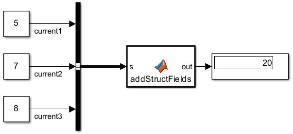
Use uint32 enumerations greater than
intmax("int32") inside MATLAB Function
blocks
Starting in R2024a, you can use MATLAB enumerations derived from base type uint32 with values greater than intmax("int32")
inside MATLAB Function blocks.
Enumerations with values greater than intmax("int32") are not
supported as input to or output from MATLAB Function blocks.
Prior to R2024a, usage in MATLAB Function blocks supported
uint32 enumeration values less than or equal to
intmax("int32") only.
Control function inlining at the function call site using
coder.inlineCall and
coder.nonInlineCall
Starting in R2024a, you can call functions using coder.inlineCall (MATLAB Coder) and coder.nonInlineCall (MATLAB Coder) to instruct the code generator whether or not to
inline the called function. The coder.inlineCall and
coder.nonInlineCall functions override coder.inline directives in the called function.
For example, you can inline function foo and prevent the inlining
of function bar in the generated code by calling
foo and bar in your MATLAB code using coder.inlineCall and
coder.nonInlineCall,
respectively.
... coder.inlineCall(foo); coder.nonInlineCall(bar); ...
The coder.inlineCall and coder.nonInlineCall
functions are subject to the same limitations as the coder.inline
directive.
Generate code for alternate execution paths depending on whether configuration settings support unbounded variable-size arrays
In R2024a, you can use the coder.areUnboundedVariableSizedArraysSupported function inside
MATLAB Function blocks. The return value of this function depends on
whether you perform model simulation or code generation.
During model simulation, this function returns the state of the configuration parameter Dynamic memory allocation in MATLAB functions.
During code generation, this function checks the state of the
configuration parameters Dynamic memory allocation in MATLAB
functions and Support: variable-size
signals. If both of these parameters are enabled, the
function returns true. Otherwise, it returns
false.
In both situations, the return value of
coder.areUnboundedVariableSizedArraysSupported indicates
whether current configuration settings support unbounded variable-size arrays.
In MATLAB execution, the
coder.areUnboundedVariableSizedArraysSupported function
always returns true.
For a demonstration of this functionality, consider the MATLAB function sumOfOneToN that computes the sum of the first
n natural numbers in two different ways.
function out = sumOfOneToN(n) if (coder.areUnboundedVariableSizedArraysSupported) out = sum(1:n); % Uses unbounded variable-size array else out = n*(n+1)/2; % Does not use unbounded variable-size array end
Model simulation with dynamic memory allocation enabled executes the
if branch in the function sumOfOneToN. This
branch uses an unbounded variable-size array to compute the output.
By contrast, model simulation with dynamic memory allocation disabled executes the
else branch in the function sumOfOneToN. This
branch does not use unbounded variable-size arrays to compute the output.
Code generation for more toolbox functions
In R2024a, you can generate code for many additional toolbox functions and objects. For a list of all functions and objects that are supported for code generation, see:
These are links to the release notes of some toolboxes that added code generation support in R2024a:
See MATLAB Coder Support: Generate C and C++ code using additional functions (Computer Vision Toolbox).
See C Code Generation: Generate code from additional functions using MATLAB Coder (Image Processing Toolbox).
See Generate C/C++ code for signal generation and spectral analysis (Signal Processing Toolbox).
See C/C++ Code Generation: Automatically generate code for wavelet functions (Wavelet Toolbox).
New High-Integrity System modeling guidelines
This table lists the high-integrity system modeling guidelines introduced in R2024a.
| Guideline | Model Advisor Check |
|---|---|
| hisl_0078: Usage of identical modeling patterns | Check usage of identical modeling patterns (Simulink Check) |
| hisl_0079: Connections to root input/output ports | Check for invalid root input and output port connections (Simulink Check) |
| hisl_0038: Configuration Parameters > Code Generation > Comments | Added configuration parameters Stateflow object comments (Simulink Coder) and MATLAB source code as comments (Simulink Coder) to the guideline. |
Removed or modified modeling guidelines
Starting in R2024a, these modeling guidelines have been removed or modified.
| Modeling Guideline | Description |
|---|---|
cgsl_0101: Zero-based indexing | Removed |
hisl_0046: Configuration Parameters > Simulation Target > Block reduction | Removed |
| hisl_0310: Configuration Parameters > Diagnostics > Model Referencing | Configuration parameter Invalid root Inport/Outport
block connection
(ModelReferenceIOMsg) is no longer supported in
the software, therefore, the parameter is removed from the modeling
guideline. |
| hisl_0037: Configuration Parameters > Model Referencing | Removed configuration parameter Pass fixed-size scalar root inputs by value for code generation from the guideline. |