Add I/O Blocks to Simulink Model
You can transform a Simulink® model into a Simulink® Real-Time™ model that accesses I/O drivers by using the Simulink Real-Time: Speedgoat I/O Blockset. This example uses the Simulink model slrt_ex_osc to show how to replace Simulink blocks with Simulink Real-Time I/O blocks.
Browse Simulink Real-Time : Speedgoat Block Libraries
1. To browse the Simulink Real-Time block library, open the Library: slrealtimelib window. In the MATLAB® Command Window, type:
slrealtimelib
2. To browse the Simulink Real-Time : Speedgoat I/O Blockset , open the Library: speedgoatlib window. In the MATLAB Command Window, type:
speedgoatlib
3. To open the model, in the MATLAB Command Window, type:
model = 'slrt_ex_osc';
open_system(model);
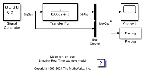
The Simulink block diagram opens for the model slrt_ex_osc.
4. Open the Simulink Library Browser. Select Simulink Real-Time: Speedgoat I/O Blockset IO131.
Drag each of these blocks to the Simulink block diagram: Speedgoat IO131 Analog input block, Speedgoat IO131 Analog output block, and Speedgoat IO131 Setup.
The Simulink Editor adds the new I/O blocks to your model.
5. Remove the Signal Generator block and add the Speedgoat IO131 Analog input block from the Speedgoat I/O Blockset in its place. Remove the Scope block and add the Speedgoat IO131 Analog output block in its place. The block parameters select the number of outputs for the block.
6. Save the model with a new name, such as ex_slrt_iob_osc. Your updated model could appear as shown.
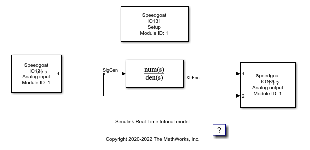
You cannot run this model unless the required Speedgoat I/O board is installed in your target computer. You can substitute driver blocks for another I/O board that is installed in the target computer.
After you add I/O blocks to the model, set up the I/O operation by selecting block parameter values. For more information, see Configure Block Parameters.
Close Model
To close the model, in the Command Window, type:
bdclose(model);