Troubleshoot an Assembly Error
In closed-loop systems, joints and constraints must be mutually compatible. For example, in a four-bar linkage, all revolute joints must spin about parallel axes. If one of the joints spins about a different axis, assembly fails and the model does not simulate.
To simplify the troubleshooting process, use Variable Viewer. This tool helps you pinpoint the joints and constraints that caused assembly to fail. Once you identify these joints and constraints, you can then determine which of their frames to correct—and how to correct them.
In this example, you identify the assembly error source in an aiming mechanism model using Variable Viewer. Then, using Multibody Explorer, you determine how to correct that error source.
Explore Model
To open the model, at the MATLAB® command line, enter:
openExample('sm/HowToBuildAMultibodyInSimulinkExample',...
'supportingFile','HowToBuildAMultibodyInSimulinkAssemblyWithError.slx')
The figure shows a schematic of the system that the model represents. This system contains four bodies, labeled A-D. These bodies connect in a closed loop via four joints, labeled Ri, Ro, Rg, and Pg. When connected to each other, these components form a system with one degree of freedom.

The model represents the components of this system using blocks. Each block represents a physical component. A World Frame block provides the ultimate reference frame in the model. The figure shows the block diagram that the model uses to represent the double-crank aiming mechanism.

To represent the bodies, the model contains four subsystem blocks, labeled Rigid Body A-D. Each subsystem contains one Cylindrical Solid block and multiple Rigid Transform blocks. The Cylindrical Solid block provides geometry, inertia, and color to the body subsystem. The Rigid Transform blocks provide the frames that you connect the joints to. A Reference Frame block identifies the ultimate reference frame in the subsystem block.
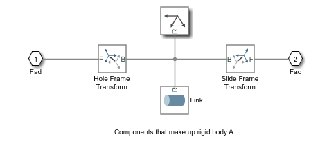
The model labels the body subsystem blocks Rigid Body A-D. To examine the block diagram for a body subsystem, right-click the subsystem block and select Mask > Look Inside Mask. The figure shows the block diagram for Rigid Body A.
To represent the joints, the model contains four joint blocks. Three joints provide one rotational degree of freedom between a pair of bodies. You represent each of these joints with a Revolute Joint block. A fourth joint provides one translational degree of freedom between a pair of bodies. You represent this joint with a Prismatic Joint block. The model labels the revolute joint blocks Ro, Rg, and Ri, and the prismatic joint block Pg.
Update Model
As the model name suggests, this model contains an error. The error prevents the model from assembling successfully, which causes simulation to fail. To update the model and investigate the assembly error. In the Modeling tab, click Update Model.
Multibody Explorer opens with a static display of your model in its initial state. Because the model contains an assembly error, Simscape™ Multibody™ issues an error message. Ignore that message for now.
Troubleshoot Assembly Error
Multibody Explorer provides access to Variable Viewer that summarizes the assembly status of each joint and constraint in a model. To open the tool, in the Diagnostics section, select Variable Viewer.
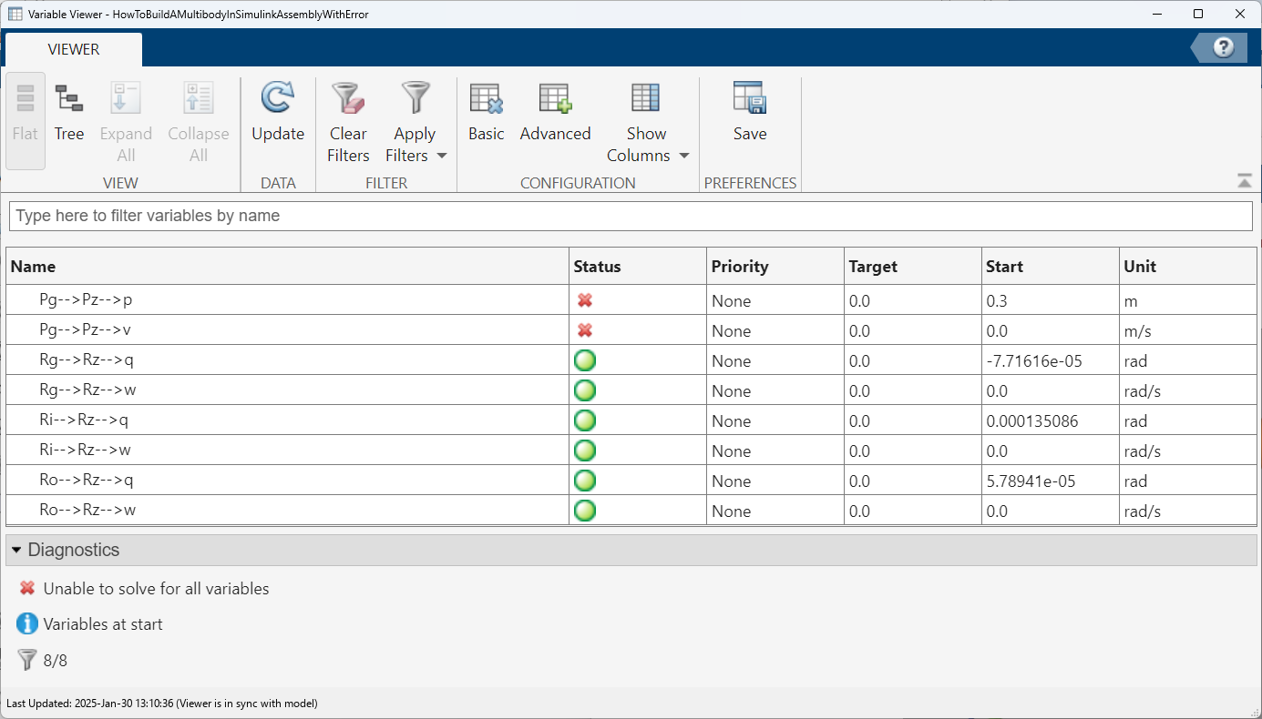
Variable Viewer opens in a new window. It shows that the Pg joint causes the model assembly error. This information enables you to concentrate your troubleshooting efforts on a small block diagram region—that surrounding the Pg joint block.
Identifying Error Root Cause
The error message that Simscape Multibody issued during model update identifies position violation as the root cause of assembly failure. This suggests that the frames connected by joint Pg are improperly aligned. To confirm this hypothesis, check the orientation of these frames in Multibody Explorer.
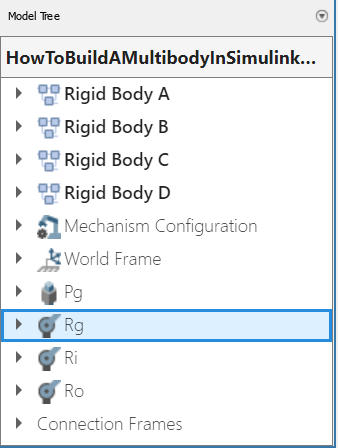
In the Multibody Explorer Model Tree pane, select Pg.
In the Multibody Explorer visualization pane, examine the position and orientation of the highlighted frames. These are the frames that appear in a light turquoise blue color.
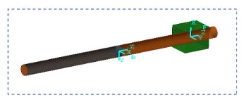
The two frames are offset along the z-axis. This offset is valid, since joint Pg contains a prismatic primitive aligned with the z-axis, providing the frames with one translational degree of freedom along that axis. However, the two frames are also rotated with respect to each other about the common z-axis. This offset is invalid, since joint Pg contains no Revolute or Spherical primitives, and hence no rotational degrees of freedom about any axis. To correct the model assembly error, you must rotate either of the two frames so that all of their axes are parallel to each other.
Correct Assembly Error
In this example, you apply a rotation transform to the follower frame so that its axes lie parallel to the base frame axes. Alternatively, you could apply an equivalent rotation transform to the base frame. This step enables joint Pg, and hence the model itself, to assemble successfully.
In the tree pane of Multibody Explorer, right-click the Pg node and select
Go To Block. Simscape Multibody brings the block diagram to the front and highlights the Pg block.Right-click the Rigid Body C subsystem block and select Mask > Look Inside Mask.
Double-click the Slide Frame Transform block and select the new parameter values that the table provides.
Parameter New Value Rotation > Pair 2 > Follower +XRotation > Pair 2 > Base +Y
Simulate Model
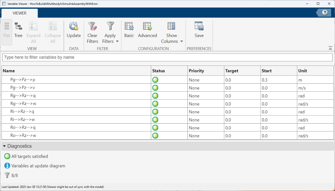
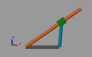
You can now simulate the model. Multibody Explorer opens with a 3-D animation of your model. The figure shows a snapshot of the animation. Rotate, roll, pan, and zoom to explore.
You can use Variable Viewer to verify the assembly status. To do this, in the Multibody Explorer, in the Diagnostics section, select Variable Viewer. In Variable Viewer, check the Diagnostics window and the Status column. The green circles indicate that the model has assembled correctly.