Measure PWM Frequency by Triggering an ISR on Arduino Hardware
This example shows you how to measure the frequency of a pulse-width modulation (PWM) signal on an Arduino® hardware using Arduino External Interrupt block. The example uses the same board to generate and detect the PWM signal. The pin 2 is connected to the pin 3 of the Arduino Mega 2560 hardware. The pin 2 generates PWM signal. When there is a rising edge at pin 3, the External Interrupt block executes a function call to calculate the time between two consecutive rising edges of the signal, which in turn is used to calculate the frequency of the signal at pin 3.
Prerequisites
Before you start this example, we recommend you complete the Get Started with Arduino Hardware example.
Required Hardware
Supported Arduino board
USB cable
Breadboard wire
Simulink Model Description
Open the arduino_measure_frequency Simulink model.
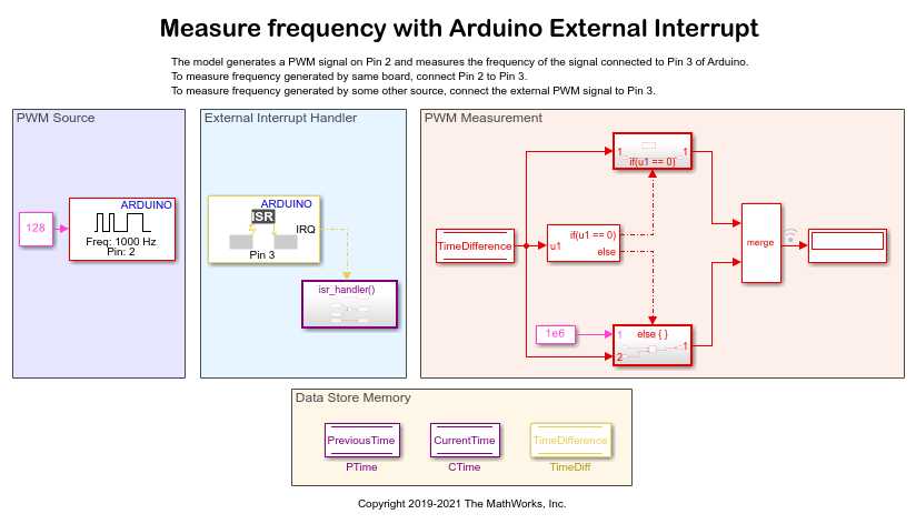
PWM Source: The PWM block is configured to generate a PWM signal with a duty cycle of 50% and a frequency of 1000 Hz on pin 2 of the hardware. The model accepts the generated signal to calculate the frequency of the generated signal. This model measures the frequency of the signal generated by the same board. To measure the frequency of the signal generated by some other source, connect the external source to pin 3 of the hardware.
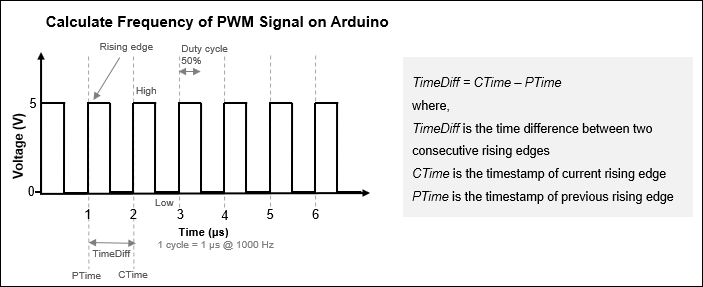
External Interrupt Handler: The External Interrupt block is configured to trigger an Interrupt Service Routine (ISR) at every rising edge of the PWM signal. When there is a rising edge on pin 3, the block executes the function call to calculate the time difference between two consecutive rising edges of the signal. The time difference is calculated using this formula and stored in the Time Difference datastore block.
TimeDiff = CTime - PTime
where: TimeDiff is the time lapse between two consecutive rising edges, PTime is the timestamp of the previous rising edge, and CTime is the timestamp of the current rising edge.
PWM Measurement: At each time step, this subsystem receives the time difference calculated by the External Interrupt Handler subsystem. If the time difference is equal to 0, it means that no signal is generated. If the time difference is greater than 0, the subsystem calculates the frequency using the formula, Frequency = 1e-6 / TimeDiff
Data Store Memory
The subsystem consist of the PreviousTime, CurrentTime, and TimeDifference Data Store Memory blocks.
Step 1: Connect Arduino Hardware
1. Connect the micro end of the USB cable to the hardware and the regular end of the USB cable to the computer. Wait until the PWR LED on the hardware starts blinking.
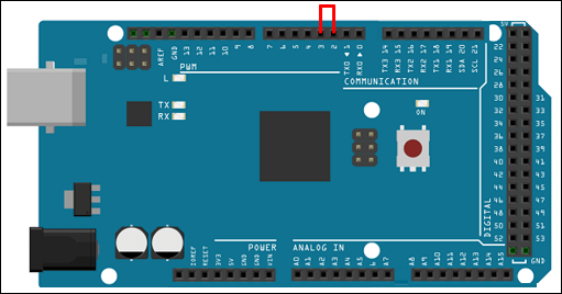
2. Connect the pulse generator pin 2 to the external interrupt pin 3 of the Arduino Mega 2650 hardware. If you are using any other supported Arduino hardware, change the pin numbers by referring to Pin Mapping for Arduino Timer Independent Blocks.
Step 2: Configure Simulink Model
1. The arduino_measure_frequency Simulink model is preconfigured to run on the Arduino Mega 2560. If you are using the Arduino Mega 2560, skip the remaining steps in this section.
2. On the Hardware tab, click the Hardware Settings button.
3. In the Configurations Parameters dialog box, select Hardware Implementation.
4. From the Hardware board list, select the type of Arduino hardware that you are using. Do not change any other settings.
5. In the Simulink model:
a. Modify the Pin number parameter of the PWM block to the pin that generates the PWM signal. In this example, the Pin Number parameter is set to 2.
b. Modify the Pin number parameter of the External Interrupt block to the pin that generates the external interrupt. In this example, the Pin number parameter is set to 3.
Step 3: Measure PWM Frequency
1. On the Hardware tab of the Simulink model, in the Mode section, select Run on board and then click Monitor & Tune. This action builds, downloads, and runs the model on the Arduino hardware. The lower-left corner of the model window displays the status while Simulink prepares, downloads, and runs the model. On successfully building the model, pin 2 generates PWM signals. On every rising edge, pin 3 generates an interrupt to calculate the time between the two consecutive rising edges of the signal, which in turn is used to calculate the frequency of the PWM signal at pin 3. The frequency of the signal is displayed on the Display block. The frequency displayed on the Display block is approximately equal to the frequency of the PWM signal generated by the PWM block.
2. To open Analyze Simulation Results, right-click the logged signal indicator icon and select Open Data Inspector. The SDI displays all the logged PWM signals for the frequency calculated at each time step.

See Also
Trigger Downstream Function-Call Subsystem Using Arduino External Interrupt Block
You can also select a web site from the following list:
Americas
- América Latina (Español)
- Canada (English)
- United States (English)
Europe
- Belgium (English)
- Denmark (English)
- Deutschland (Deutsch)
- España (Español)
- Finland (English)
- France (Français)
- Ireland (English)
- Italia (Italiano)
- Luxembourg (English)
- Netherlands (English)
- Norway (English)
- Österreich (Deutsch)
- Portugal (English)
- Sweden (English)
- Switzerland
- United Kingdom (English)