Obstacle Detection Using Ultrasonic Sensor with the VEX Microcontroller
This example shows you how to use Simulink® Coder™ Support Package for ARM® Cortex®-based VEX® Microcontroller to interface the VEX ultrasonic sensor to the VEX Microcontroller and use the sensor data to control a 4-wheeled robot.
Introduction
Simulink Coder Support Package for ARM Cortex-based VEX Microcontroller enables you to create and run Simulink models on a VEX microcontroller.
In this example, you will learn how to verify the output of Ultrasonic sensor block and create a model that reads the output of VEX Ultrasonic sensor and use this value to control the motion of a 4-wheeled robot. The 4 wheels are powered by 2 DC motors which are connected to a VEX Microcontroller. The Simulink model will read the distance value from the Ultrasonic sensor and provide appropriate speed input to the DC motors to drive the robot.
Prerequisites
If you are new to Simulink, we recommend watching the Simulink Quick Start video.
We recommend completing Getting Started with VEX Microcontroller Support Package.
Required Hardware
To run this example, you will need the following hardware:
ARM Cortex-based VEX Microcontroller
VEXnet Gamepad and VEXnet keys
Standard DC Motors (2) and Motor Controller 29 (2)
4-wheel robot platform
7.2V Battery
USB type A-Male to A-Male cable
Below is a figure of a 4-wheel robot platform with Ultrasonic sensor connected and 2 DC motors connected to the 2 wheels and attached to a VEX microcontroller.

Verification of Ultrasonic Sensor Block
Task 1 - Hardware Connections
1. Connect the VEX Microcontroller to your computer with a USB cable.
2. Plug the connector labelled 'INPUT' of the VEX Ultrasonic sensor to digital port 1 on the VEX Microcontroller.
3. Plug the connector labelled 'OUTPUT' of the VEX Ultrasonic sensor to digital port 2 on the VEX Microcontroller.
4. Connect the battery supply to the VEX Microcontroller.
Task 2 - Perform parameter tuning and verify the Ultrasonic sensor block
In this task, you will perform signal monitoring and parameter tuning to read the distance from the Ultrasonic sensor and display it on the Display block.

1. Open the pre-configured vexarmcortex_ultrasonic_externalmode model. In this model, the output of Ultrasonic Sensor block is connected to the input of a Display block. Make sure that the parameter values for INPUT (Ping Port) and OUTPUT (Echo Port) of Ultrasonic Sensor block are chosen according to the sensor connection in Task 1.
2. See Signal Monitoring and Parameter Tuning to prepare and run this model for parameter tuning.
3. While the model is running, place an object at a certain distance from the VEX Ultrasonic sensor and observe the distance value on the Display block in the Simulink model. Observe that the distance value increases when the object is moved away from the sensor and decreases when the object is moved towards the sensor.
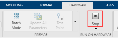
4. Press the Stop button in the Hardware tab to terminate the External mode simulation.
In Task 1 and 2, you learned how to connect the VEX Ultrasonic sensor to the VEX microcontroller and verify the distance value read by the Ultrasonic Sensor block while performing Monitor and Tune action.
Obstacle Detection Robot Using Ultrasonic Sensor
In this task, you will learn how to use the Ultrasonic Sensor to control the motion of a 4-wheeled robot when an obstacle is encountered. The robot moves at a constant speed if there is no obstacle in front or if the obstacle is more than 0.5 m away. It stops when the distance to the obstacle is 0.2 m or less.
Task 3 - Hardware Connections
1. Perform all the steps mentioned in Task 1 above.
2. The two DC motors drive the left and right set of wheels on the robot platform. Connect the two DC motor pins on the VEX microcontroller. The motor connected to the left wheel should be connected to the motor pin 6, and the motor connected to the right wheel to pin 3. Use the Motor Controller 29 cables to establish the connection between the motors leads and the pins on VEX Microcontroller. Connect them as described on Page 4 of the VEX Microcontroller and VEXnet Joystick User Guide.
Task 4 - Build and download the Simulink model for Obstacle Detection using Ultrasonic Sensor
In this task, you will learn a way to model the logic for using the Ultrasonic Sensor block output to control the speed of the two DC motors, thereby controlling the motion of the robot. The logic for controlling the motor speed is implemented in a Stateflow chart. You will then build and download the model to the VEX microcontroller.

1. Open the pre-configured vexarmcortex_ultrasonicsensor model.
2. Note the following points in this Simulink model:
The parameters INPUT (Ping Port) and OUTPUT (Echo Port) for the Ultrasonic Sensor block is chosen as per the hardware connections in Task 3. The parameter Motor Channel for the Left Motor block is chosen as '6' and for the Right Motor block as '3' as per the hardware connections in Task 3.
The average value of three samples of the Ultrasonic Sensor block output is used for determining the distance to the obstacle.
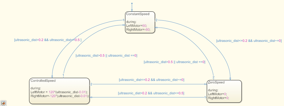
The logic for motion control based on Ultrasonic sensor is implemented in the Stateflow® chart as shown below. The speed input to the DC Motors is a constant value of 60 when the average value of Ultrasonic Sensor block output is either 0 or more than 0.5. The speed input to the motors is reduced when the sensor value is between 0.5 and 0.2. The motors are stopped by providing a speed input of 0 if the sensor value is less than 0.2.
See Getting Started with Stateflow for an introduction to implementing states in Stateflow.
3. In the Simulink model, go to the Modeling tab and click Model Settings.

4. When the Configuration Parameters page opens up, navigate to the Hardware Implementation pane.
Set the Hardware board to ARM Cortex-based VEX Microcontroller.
5. In the Configuration Parameters page, navigate to Solver pane and set the Solver to discrete (no continuous states).
6. Click OK.
7. Before building the model, make sure to connect the VEX Microcontroller to your computer with a USB A-Male to A-Male cable.
8. In the Simulink model, go to the Hardware tab and click Build, Deploy & Start. The model will now be deployed to the VEX microcontroller.

9. Disconnect the USB cable from the VEX microcontroller and connect the VEXnet key to the VEX microcontroller. Turn ON the VEX microcontroller and Gamepad. Once the VEXnet keys are paired, the robot begins to move. Place an object at some distance in front of the robot and observe that the robot stops moving once it is 0.2 m away from the object. Increase the distance between the robot and the object and observe that the robot starts moving again until the distance between them is 0.2 m or less.
You can also select a web site from the following list:
Americas
- América Latina (Español)
- Canada (English)
- United States (English)
Europe
- Belgium (English)
- Denmark (English)
- Deutschland (Deutsch)
- España (Español)
- Finland (English)
- France (Français)
- Ireland (English)
- Italia (Italiano)
- Luxembourg (English)
- Netherlands (English)
- Norway (English)
- Österreich (Deutsch)
- Portugal (English)
- Sweden (English)
- Switzerland
- United Kingdom (English)