Code Verification and Validation with External Mode
This example shows you how to use Simulink® Coder™ Support Package for NXP™ FRDM-K64F for code verification and validation using External mode.
Introduction
In this example you will learn how to configure a Simulink model to run a simulation in External mode.
Simulink's External mode feature enables you to accelerate the process of parameter tuning by letting you change certain parameter values while the model is running on target hardware, without stopping the model. When you change parameter values from within Simulink, the modified parameter values are communicated to the target hardware immediately. The effects of the parameters tuning activity may be monitored by viewing algorithm signals on scopes or displays in Simulink.
This example introduces the Simulink code generation and verification workflow by showing you how to:
Configure a Simulink model to run a simulation in External mode
Prerequisites
We recommend completing the Getting Started with Simulink Coder Support Package for NXP FRDM-K64F Board example.
Required Hardware
To run this example you will need the following hardware:
NXP FRDM-K64F
USB type A to Micro-B cable
open_system('freedomk64f_external_mode');
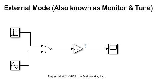
Task 1 - External Mode
In this task, you will run a model in External mode. When you are prototyping and developing an algorithm, it is useful to monitor and tune the algorithm while it runs on hardware. The External mode feature in Simulink enables this capability.
It is recommended to use the Segger's J-Link OpenSDA V2 firmware on your hardware board to run the external mode simulation. The Segger firmware has enhanced data transfer and debugging abilities. For example, baudrates for external mode simulations can be in excess of 115200 bits/sec.
If you would like to update your FRDM-K64F board with Segger J-Link firmware, follow the steps described in the section Install Segger J-Link Firmware on FRDM-K64F Board.
The External mode simulation uses serial communication over a USB interface. To set up the serial communication:
1. Connect the NXP FRDM-K64F Board to your computer with a USB cable.
2. Open the External mode model. This model has already been configured for the NXP FRDM-K64F target. To learn how to setup a model for this target please see the Model Configuration Parameters for NXP FRDM-K64F Board.
3. Configure the model for External mode:
Navigate to Hardware Implementation pane in the Configuration Parameters dialog.
Click on the External mode group.
Select the Communication interface as Serial.
Enter the Baudrate to be used for the External mode communication. If you are using the firmware image from Segger, you may use Baudrates in excess of 115200
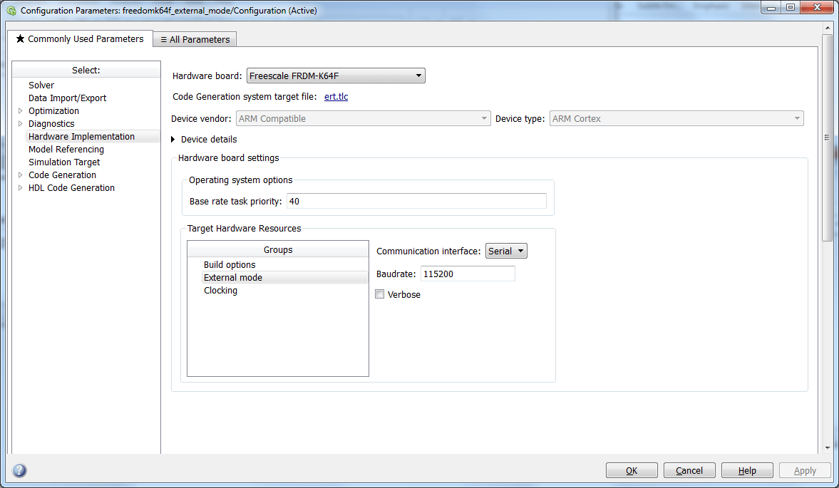
4. Click Apply and close the configuration parameters window.
5. Select the signals that you would like to instrument. It is recommended that you instrument signals by streaming them to the Simulation Data Inspector rather than by using Scope blocks for the following reasons:
Streaming does not store data in memory, making more efficient use of the memory available on the hardware. Scope blocks store data in buffers before sending the data to the host.
You can stream signals from top models and reference models simultaneously. Scope blocks can only log signals from a top level model.
Note: Data streamed to the Simulation Data Inspector is unaffected by Set Up External Mode Connectivity Between Simulink and Target Hardware. As a result, external mode parameters such as Duration (ExtModeTrigDuration) and Delay (ExtModeTrigDelay) will have no effect on the data from signals being streamed to the Simulation Data Inspector.
If you have a model with logged signals and only want to stream them, then you can convert the logged signals to streamed signals using the Simulink.sdi.markSignalForStreaming
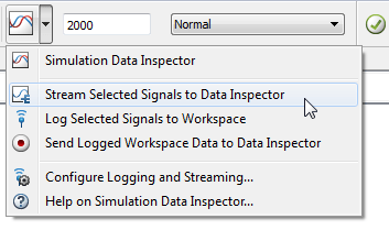
To stream data from your model into the Simulation Data Inspector:
Select one or more signals in the model.
On the Simulink Editor toolbar, click the Simulation Data Inspector button arrow and select Stream Selected Signals to Data Inspector to mark the signal for streaming.
A streaming badge is shown above the signals in the model that have been marked for streaming.

6. Go to Hardware tab and click Monitor & Tune
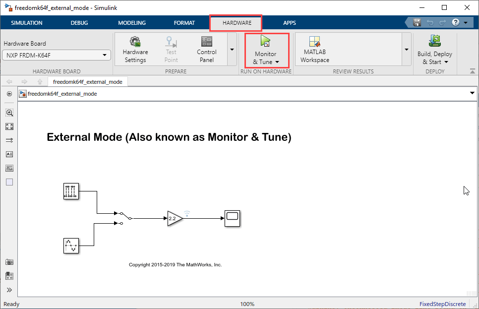
Wait for the model to finish getting built and downloaded onto the target. Once this is done, the External mode simulation will begin. Double click the Manual Switch block while simulation is running to change the input source. Double click on the Gain block to change the signal gain. Finally, double click on the Scope block to view the External mode simulation results. Note that the entire model is running on the target.
If a signal had been selected for streaming to the Simulation Data Inspector, a new simulation run appears in the Compare Runs of the Simulation Data Inspector. During simulation, the Simulation Data Inspector button appears highlighted to indicate that new simulation output is available in the Simulation Data Inspector.

7. Stop Monitor & Tune simulation:
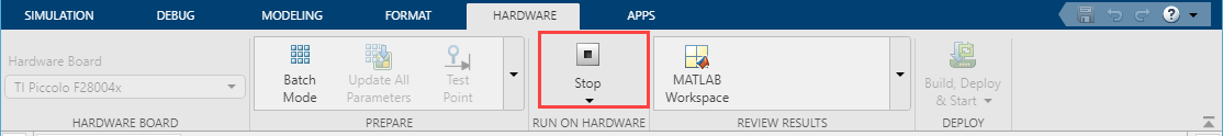
Stopping External mode simulation terminates code running on the NXP FRDM-K64F. Before you can start another External mode simulation you need to run the generated code again. You can re-run the generated code by simply pressing the reset button on the NXP FRDM-K64F.
You can also select a web site from the following list:
Americas
- América Latina (Español)
- Canada (English)
- United States (English)
Europe
- Belgium (English)
- Denmark (English)
- Deutschland (Deutsch)
- España (Español)
- Finland (English)
- France (Français)
- Ireland (English)
- Italia (Italiano)
- Luxembourg (English)
- Netherlands (English)
- Norway (English)
- Österreich (Deutsch)
- Portugal (English)
- Sweden (English)
- Switzerland
- United Kingdom (English)