Getting Started with Simulink Coder Support Package Using STMicroelectronics Nucleo Boards
This example demonstrates how to use the Simulink® Coder™ Support Package for STMicroelectronics® Nucleo Boards to run a Simulink® model on an STMicroelectronics Nucleo board.
Simulink Coder Support Package for STMicroelectronics Nucleo Boards enables you to create and run Simulink models on supported STMicroelectronics Nucleo boards. The support package includes a library of Simulink blocks for configuring and accessing STMicroelectronics Nucleo peripherals and communication interfaces.
In this example you will learn how to configure a simple Simulink model to generate code for STMicroelectronics Nucleo F401RE board and run the generated code on the board to periodically turn an LED on and off. You can configure this model for other supported Nucleo boards by browsing to Configuration Parameters > Hardware Implementation > Hardware board and selecting the required board.
Available models for this example:
STM Nucleo: GettingStartedSTMNucleo.slx
Prerequisites
If you are new to Simulink, we recommend completing the Interactive Simulink Tutorial.
If you are new to Simulink Coder, visit the Simulink Coder product page for an overview and tutorials.
If you have not yet installed ST-Link/V2 USB drivers, follow the steps as described in Install Drivers for the Simulink Coder Support Package for STMicroelectronics Nucleo Boards.
For code generation, you can either select GNU Tools for ARM Embedded Processors or Armclang Compiler toolchain. For more information, see Set Up and Configure Armclang Compiler Toolchain for Code Generation.
Required Hardware
To run this example you will need the following hardware:
Supported STMicroelectronics Nucleo boards
USB cable
Configure Model for Code Generation and Download
In this task, you will configure a simple model to run on the STMicroelectronics Nucleo board.
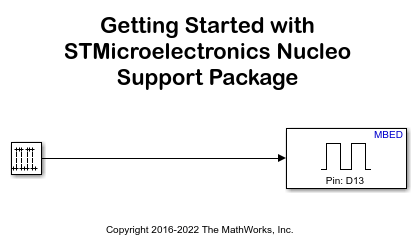
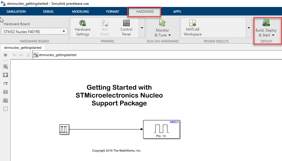
1. Open the LED model. This model has been configured for the Nucleo F401RE board.
2. Open the Modeling tab and press CTRL+E to open Configuration Parameters dialog box.
3. Go to Hardware Implementation > Hardware board.
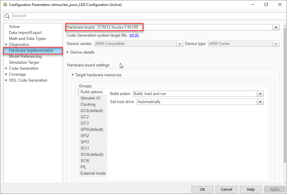
4. The user LED is driven by GPIO Pin 13 on the Nucleo F401RE board. The user LED might be driven by a different Pin on different Nucleo boards.
5. Open Hardware tab and click on Build, Deploy & Start to automatically download the generated bin file, GettingStartedSTMNucleo.bin, on to the connected Nucleo board.
6. You will see in the Diagnostic Viewer window that code is generated and downloaded on to the connected board for the model.
..
.....
......
### Created: ../GettingStartedSTMNucleo.elf
### Invoking postbuild tool Binary Converter ...
arm-none-eabi-objcopy -O binary ../GettingStartedSTMNucleo.elf ../GettingStartedSTMNucleo.bin
### Done invoking postbuild tool.
### Invoking postbuild tool Hex Converter ...
arm-none-eabi-objcopy -O ihex ../GettingStartedSTMNucleo.elf ../GettingStartedSTMNucleo.hex
### Done invoking postbuild tool.
### Invoking postbuild tool Executable Size ...
arm-none-eabi-size ../GettingStartedSTMNucleo.elf
   text	   data	    bss	    dec	    hex	filename
   4264	    196	   8308	  12768	   31e0	../GettingStartedSTMNucleo.elf
### Done invoking postbuild tool.
### Successfully generated all binary outputs.
### Downloading executable to the hardware on Drive: G:
      1 file(s) copied.
### Successful completion of build procedure for model: GettingStartedSTMNucleo
### Creating HTML report file stmnucleo_gettingstarted_codegen_rpt.html
Build process completed successfully
7. Observe that the LED turns ON for 0.5 second and switches OFF for 0.5 second periodically.
On the Nucleo board the binary file generated can be manually copied to the drive connected to Nucleo board.
Observe that the green LED turns ON for 0.5 second and switches OFF for 0.5 second periodically.
Configure the Model for the Build
In this task, you will configure a simple model to build and generate out file for the STMicroelectronics Nucleo board.
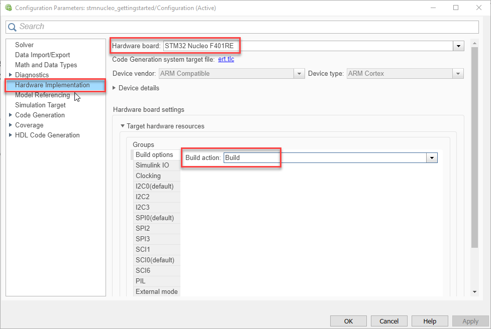
1. Open the LED model corresponding to the target hardware from above.
2. The user LED is driven by GPIO Pin 13 on the Nucleo F401RE board.
3. Change the Build action to Build to only generate the hex,bin and elf executable files. Follow the steps below to set the Build action:
4. Open the Hardware tab and click Build, Deploy & Start to Generate code for the model.
5. You will see in the Diagnostic Viewer window that code is generated.
..
.....
......
### Created: ../GettingStartedSTMNucleo.elf
### Invoking postbuild tool Binary Converter ...
arm-none-eabi-objcopy -O binary ../GettingStartedSTMNucleo.elf ../GettingStartedSTMNucleo.bin
### Done invoking postbuild tool.
### Invoking postbuild tool Hex Converter ...
arm-none-eabi-objcopy -O ihex ../GettingStartedSTMNucleo.elf ../GettingStartedSTMNucleo.hex
### Done invoking postbuild tool.
### Invoking postbuild tool Executable Size ...
arm-none-eabi-size ../GettingStartedSTMNucleo.elf
  text	   data	    bss	    dec	    hex	filename
  4264	    196	   8308	  12768	   31e0	../GettingStartedSTMNucleo.elf
### Done invoking postbuild tool.
### Successfully generated all binary outputs.
C:\GettingStartedSTMNucleo_ert_rtw>exit /B 0
### Successful completion of build procedure for model: GettingStartedSTMNucleo
6. You can manually copy the "bin" file generated to the drive letter connected to the hardware.
Review Block Library for Your Board
The Simulink Coder Support Package for STMicroelectronics Nucleo Boards provides an easy way to create algorithms that use peripherals supported by the hardware. Dedicated blocks are provided in the block library that can be added to your Simulink model. Use these blocks to configure the associated sensors and actuators, read data from a peripheral or send data to a peripheral.
1. Enter slLibraryBrowser at the MATLAB® prompt. This opens the Simulink Library Browser.
2. In the Simulink Library Browser, navigate to Simulink Coder Support Package for STMicroelectronics Nucleo Boards and open the Digital Write block:
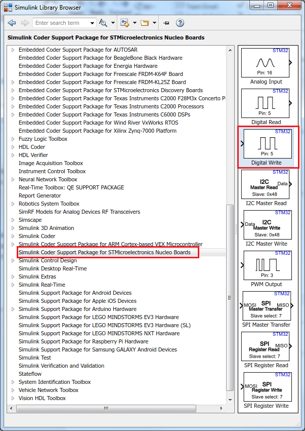
Review the block mask, which contains a description of the block and parameters for configuring the associated STMicroelectronics Nucleo digital output pin.
You can also select a web site from the following list:
Americas
- América Latina (Español)
- Canada (English)
- United States (English)
Europe
- Belgium (English)
- Denmark (English)
- Deutschland (Deutsch)
- España (Español)
- Finland (English)
- France (Français)
- Ireland (English)
- Italia (Italiano)
- Luxembourg (English)
- Netherlands (English)
- Norway (English)
- Österreich (Deutsch)
- Portugal (English)
- Sweden (English)
- Switzerland
- United Kingdom (English)