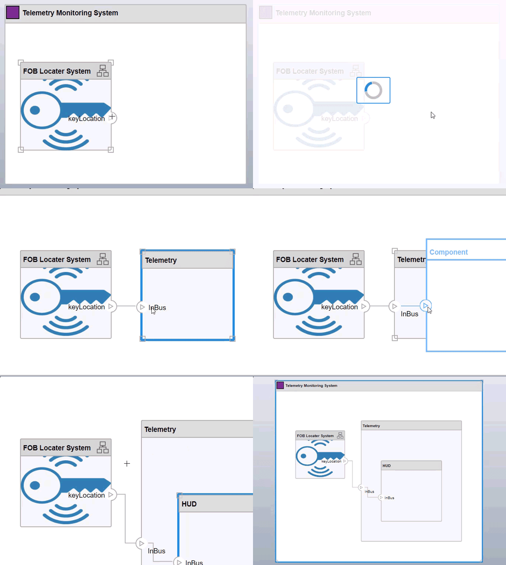
In R2024b, you can edit your System Composer™ model from the component diagram canvas in the Architecture Views Gallery. Add, edit, and delete components, ports, and connectors in the model through your view. You can also edit multiple hierarchies at the same time using component diagram views.
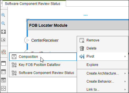
To change between views editing and model editing, right-click a component in a view and use the context menu to pivot from the component in your view to the corresponding component in your architecture model by selecting Pivot > Composition.
For more information, see Author Architecture Models Through Component Diagram Views.
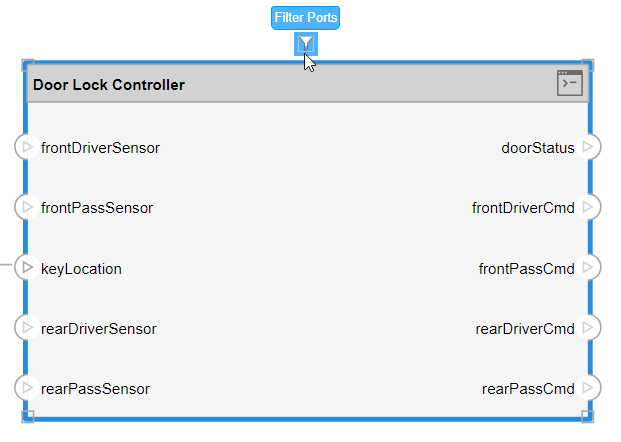
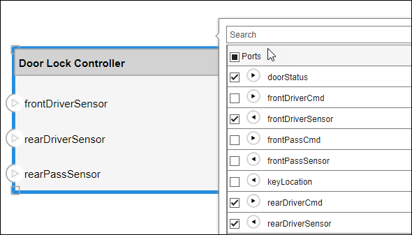
To filter ports on a component in a view in the Architecture Views Gallery, click and highlight your component. A blue box appears above the component. Pause on the ellipsis (…) that appears to select Filter Ports.
Use the check boxes to choose which ports to show and hide on your component in the view.
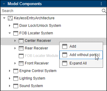
You can also add components to the view interactively without ports.
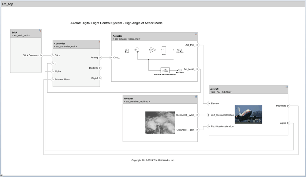
Starting in R2024b, you can link components to functional mock-up unit (FMU) files in System Composer to create an FMU behavior. System Composer preserves the architectural data on an FMU in the architecture model so that an FMU component is compatible with the rest of the architecture model. Multiple FMU components that link to the same FMU file share information such as applied profiles and stereotypes. The FMU file contains information about ports and interfaces. On the FMU architecture, this information is read-only because FMU file editing is not supported.
For more information about linking to an FMU file, see Link to Existing FMU Files and linkToFMU.
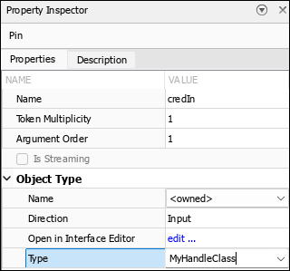
Starting in R2024b, you can model tokens that carry MATLAB® class objects. You can use a predefined MATLAB class or you can define your own MATLAB class. For more information on MATLAB classes, see User-Defined Classes.
In activity diagrams, to associate a MATLAB class with a pin that inputs or outputs tokens:
In the property Inspector for Name of the Object Type select
<owned>.Specify the Type as the MATLAB class name.
For the Action Node with MATLAB function behavior, these input and output tokens appear as input and output arguments of the MATLAB function.
For more information, see Model Complex Objects in Activity Diagrams Using MATLAB Class Tokens.
New animations that color the borders of action nodes and pins enable you to visually distinguish their state at the time of simulation. For more information, see Validate Activity Diagram Behavior Using Animations.
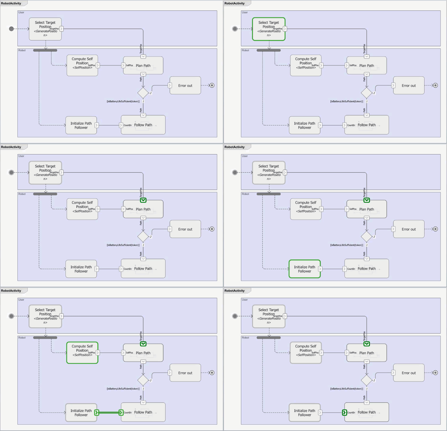
Starting in R2024b, you can inspect the contents of a pin or parameter node during simulation using the Token Inspector. When you pause the simulation and click a pin, the Token Inspector displays information on the tokens inside the pin, such as the token ID, the number of tokens in the pin, and the token payload.
For more information, see Inspect Tokens Using Token Inspector.

In an activity diagram, you can now automatically match pins on an Action Node to function arguments on the linked MATLAB function. Matching pins with arguments controls the expected behavior of the action node using the linked MATLAB function.
For example, start with the MATLAB function sound and link it to an action node in your
activity
diagram.
function [data,wave] = sound(vol,info)
     %sound Transmit sound through a speaker
     wave = vol*info;
     data = info*5;
end
To match the names and numbers of input and output pins on the action node with the numbers of input and output arguments in the linked MATLAB function, right-click the action node, and from the context menu, select the menu option Match action pins to MATLAB function arguments.
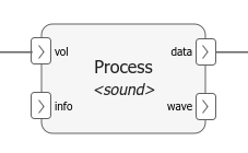
For more information, see Match Action Node Pins to MATLAB Function Arguments.
Starting in R2024b, you can author call and response messages between lifelines with client and server ports.
A client sends a call message to a server to invoke a service.
Call messages are represented by a solid line with a solid arrowhead.
A server provides a response message to a client.
Response messages are represented by a dashed line with a line arrowhead.
![A sequence diagram with two lifelines, Controller and Sensor1. There is a call message from Controller to Sensor1 with message label reset[resetData==true] and a response message from Sensor1 to Controller with message label fetchData[data>1].](sequence-diagram-client-server-messages.png)
For more information, see Describe Client-Server Interactions Using Sequence Diagrams.
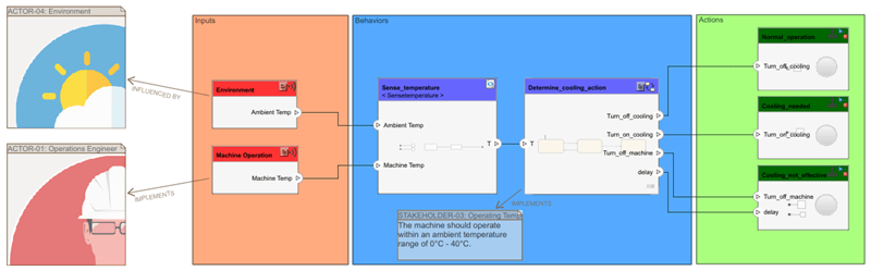
In R2024b, you can access the new Validate Requirements for Machine Cooling System Architecture example.
Open the scMachineCoolingExample project to learn about different
methods to validate requirements against stakeholder needs. The project demonstrates
how to evidence requirements verification to increase confidence in valid system
behavior.
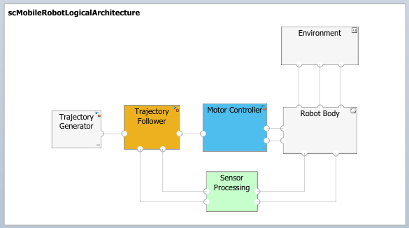
Starting in R2024b, when you zoom out of an architecture model or architecture view, the diagram changes to a low-fidelity view to improve readability.
Starting in R2024b, you can drag to add a Reference Component block linked to a model or subsystem into a System Composer model. Drag a model or subsystem file from the file explorer to add a reference component to the architecture model canvas.
For example, dragging a Simulink® model SLX file into the architecture model canvas adds a Reference Component block that references the model in the SLX file.
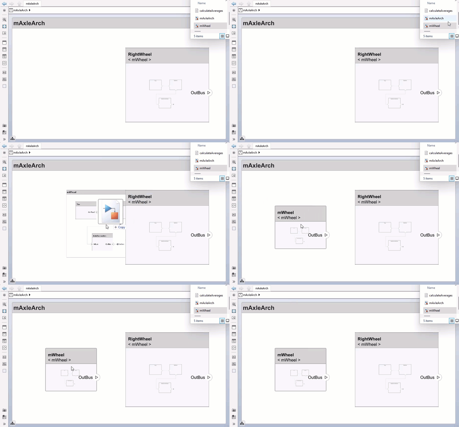
Files that you drag to add must be on the MATLAB path. Creating reference components by dragging files from the MATLAB Editor into the model canvas is not supported.
You can now change the default font in your component headers, linked model or subsystem
names, port names, and subsystem component line labels. To modify your font choices, open
the Font Styles dialog box. From the System Composer toolstrip, select Format > Fonts for Model from the down arrow next to the Font button  .
.

Starting in R2024b, you can schedule the order of component initialization for reference components in software architectures from the Initialize tab of the Functions Editor.
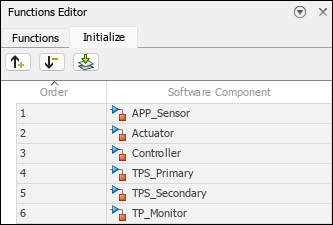
For more information, see Schedule Component Initialization in Software Architectures.