HDL OFDM MATLAB References
This example shows how to model OFDM transmitter, additive white Gaussian noise (AWGN), and OFDM receiver hardware algorithms in MATLAB® as steps toward developing a Simulink® implementation for hardware.
This bridges the gap between a mathematical algorithm and its hardware implementation. This example provides MATLAB references of the HDL OFDM Transmitter, HDL AWGN, and HDL OFDM Receiver algorithms. You can use these MATLAB references to generate test vectors for verifying the HDL implementation of the HDL OFDM Transmitter, HDL Implementation of AWGN Generator, and HDL OFDM Receiver Simulink models. This example also provides error vector magnitude (EVM) measurement functionality in Simulink to collectively evaluate the performance of transmitter and receiver.
HDL OFDM Transmitter MATLAB Reference
This section describes the MATLAB reference of HDL OFDM Transmitter.
This MATLAB reference accepts a modulation order, code rate index, number of frames, and data bits to be transmitted as a txParam structure or array of structures. txParam has these fields.
modOrder— Specify 2, 4, 16, or 64 for 'BPSK', 'QPSK', '16QAM', and '64QAM', respectively. The default value is 4 ('QPSK').codeRateIndex— Specify 0, 1, 2, or 3 for the rates '1/2', '2/3', '3/4', and '5/6' respectively. The default value is 0 ('1/2').numFrames— Specify a positive integer. The default value is 5.txDataBits— Specify binary values in a row or column vector of lengthtrBlkSizextxParam.numFrames. The default value is a column vector containing randomly generated binary values of lengthtrBlkSizextxParam.numFrames.
Calculate the transport block size (trBlkSize) by using these parameters.
numSubCar— Number of subcarriers per symbolpilotsPerSym— Number of pilots per symbolnumDataOFDMSymbols— Number of data OFDM symbolsbitsPerModSym— Number of bits per modulated symbolcodeRate— Punctured code ratedataConvK— Constraint length of the convolutional encoderdataCRCLen— CRC length
trBlkSize = ((numSubCar - pilotsPerSym) x numDataOFDMSymbols x
bitsPerModSym x codeRate) - (dataConvK-1) - dataCRCLen
For example, to generate a time-domain OFDM transmitter waveform of 5 frames with a modulation scheme of 16-QAM and code rate of 1/2 using random data bits in the transport block, format the inputs as a structure.
txParam.modOrder = 16; % Modulation order corresponding to 16-QAM
txParam.codeRateIndex = 0; % Code rate index corresponding to 1/2
txParam.numFrames = 5; % Number of frames to be generated

% Calculate transport block size (trBlkSize) using parameters
numSubCar = 72; % Number of subcarriers per symbol
pilotsPerSym = 12; % Number of pilots per symbol
numDataOFDMSymbols = 32; % Number of data OFDM symbols
bitsPerModSym = log2(txParam.modOrder); % Bits per modulated symbol
codeRate = 1/2; % Punctured code rate
dataConvK = 7; % Constraint length of convolutional code polynomial
dataCRCLen = 32; % Data CRC length
trBlkSize = ((numSubCar-pilotsPerSym)*numDataOFDMSymbols* ...
    bitsPerModSym*codeRate) - (dataConvK-1) - dataCRCLen;
txParam.txDataBits = randi([0 1],txParam.numFrames*trBlkSize,1);

% Generate complex baseband transmitter waveform
fprintf('\n-------------------------\n');
fprintf('\n Transmitting %d frames ...\n',txParam.numFrames);
[txWaveform,txGrid,txDiagnostics] = whdlexamples.OFDMTx(txParam);
fprintf('\n Transmission successful.\n');
fprintf('\n-------------------------\n');
-------------------------

 Transmitting 5 frames ...

 Transmission successful.

-------------------------
The whdlexamples.OFDMTx function returns arguments txWaveform, txGrid, and txDiagnostics.
txWaveformis the generated time-domain waveform and is returned as a column vector of length ((fftLen+cpLen) xtxParam.numFramesxnumSymPerFrame), wherefftLenis the FFT length,cpLenis the cyclic prefix length,txParam.numFramesis the number of OFDM frames generated,numSymPerFrameis the number of OFDM symbols per frame.
The frame structure of the generated time-domain waveform txWaveform is similar to the Simulink HDL OFDM Transmitter output waveform. For the detailed explanation of the frame structure, see the HDL OFDM Transmitter example.
txGridis the transmitter grid output and is returned as a matrix of sizenumSubCar-by-(txParam.numFramesxnumSymPerFrame), wherenumSubCaris the number of active subcarriers.
txDiagnosticsis a structure or array of structures and consists of these four fields:
headerBitsrepresents the header bits as a column vector of size 14, which includes 3 bits for the FFT length index, 2 bits for the symbol modulation type, 2 bits for the code rate index, and 7 spare bits.dataBitsrepresents actual data bits transmitted in the given number of frames (txParam.numFrames). This field is a binary-valued row or column vector of length equal to (txParam.numFramesxtrbBlkSize). WhetherdataBitsis a row or column vector depends on the dimension oftxParam.dataBits. The default size is a column vector of length equal totxParam.numFramesxtrbBlkSize.ofdmModOutrepresents the OFDM modulator output as a column vector of length equal to (fftLen+cpLen) xtxParam.numFramesxnumSymPerFrame.symbolModOutrepresents the symbol-modulated output as a matrix of size (((numSubCar-pilotsPerSym) xnumDataOFDMSymbols),txParam.numFrames) based on the selected inputmodOrder.
whdlexamples.OFDMTx function is used to generate OFDM transmitter waveform with synchronization, reference, header, pilots, and data signals. This function returns txWaveform, txGrid, and txDiagnostics using transmitter parameter structure txParam. This function internally calls these individual functions.
generateOFDMSyncSignal— Generates the synchronization signalSyncSignal. This function uses Zadoff-Chu sequence with a root index of 25 and length of 62.
generateOFDMRefSignal— Generates the reference signalrefSignalfor the given FFT lengthfftLen. This function uses a BPSK-modulated pseudo random binary sequence.
generateOFDMPilotSignal— Generates the pilot signalpilot. This function uses a BPSK-modulated pseudo random binary sequence.
OFDMSymbolModulate— Modulates input bits to complex modulation symbols based on the specified modulation scheme BPSK, QPSK, 16-QAM, and 64-QAM.
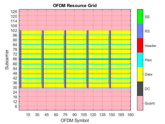
Plot the resource grid of the transmitter waveform. The plot indicates the magnitude variations of each resource grid element.
plotResourceGrid(txGrid);
HDL AWGN MATLAB Reference
This section describes the MATLAB reference of HDL AWGN.
This MATLAB reference is used to evaluate the performance of the HDL OFDM Transmitter and Receiver algorithms. The HDL AWGN MATLAB reference generates AWGN by accepting the signal-to-noise ratio (SNR) in decibel (dB) and sets of seeds. For more details, see HDL Implementation of AWGN Generator. The generated AWGN is added to the HDL OFDM Transmitter output.
FFTLen = 128;
CPLen = FFTLen/4;
usedSubCarr = 72; % Out of 128 subcarriers, 72 subcarriers are loaded with data

SNRdB = 30;
SNRdBSimInput = SNRdB*ones(length(txWaveform)+633,1);
seedsURNG1 = [121 719 511]; % Seeds for TausURNG1
seedsURNG2 = [2343 323 833]; % Seeds for TausURNG2
txScaleFactor = FFTLen/sqrt(usedSubCarr);

awgnNoise = whdlexamples.hdlawgn(SNRdBSimInput,seedsURNG1,seedsURNG2);

% 633 initial samples of the noise are discarded to match the MATLAB data
% with that of the Simulink model
rxWaveform = txWaveform + (1/txScaleFactor)*awgnNoise(634:end);
fprintf('\n Applying the AWGN channel at %d dB...\n', SNRdB);
Applying the AWGN channel at 30 dB...
HDL OFDM Receiver MATLAB Reference
This section describes MATLAB reference of HDL OFDM Receiver.
This MATLAB reference includes time synchronization, CFO estimation and correction, OFDM demodulation, header recovery, CPE estimation and correction, and data recovery.
The whdlexamples.OFDMRx function accepts rxWaveform, a transmitted waveform passed through an AWGN channel.
The whdlexamples.OFDMRx function returns decoded bits rxBits and an array of structures, rxDiagnostics, consisting of these eight fields.
estCFO— Estimated carrier frequency offsetrxConstellationHeader— Demodulated header constellation symbolsrxConstellationData— Demodulated data constellation symbolssoftLLR— Demodulated soft LLR bitsdecodedCodeRateIndex— Decoded code rate index from headerdecodedModOrder— Decoded modulation order from headerheaderCRCErrorFlag— Status of header CRCdataCRCErrorFlag— Status of data CRC
OFDMRx
The whdlexamples.OFDMRx function is used to demodulate and decode the received rxWaveform. This function internally calls these individual functions.
OFDMFrequencyOffset— Estimates the carrier frequency offset based on cyclic prefix (CP) technique. The cyclic prefix portion of the received time-domain waveform is correlated to estimate frequency offset.
OFDMFrequencyCorrect— Corrects the carrier frequency offset on the received waveform using the estimated frequency offset.
OFDMFrameSync— Synchronizes the received waveform by performing correlation using the reference signal. This step reduces the intersymbol interference while demodulating the received waveform.
OFDMDemodulation— Converts the time-domain waveform to frequency-domain waveform for further decoding. The objectdsp.HDLFFTis used for HDL implementation of the receiver.
OFDMChannelEstimation— Performs the estimation of the channel using two reference signals. It uses least squares (LS) estimation technique. LS estimates are averaged to improve channel estimation accuracy.
OFDMChannelEqualization— Performs zero forcing (ZF) equalization using the estimated channel. Then the received waveform that is free of the channel is used for header recovery and data recovery.
OFDMHeaderRecovery— Recovers header information by performing symbol demodulation, deinterleaving, and Viterbi decoding. The CRC status indicates the success or failure of header information recovery. This header recovery CRC status is given as an output of the receiver to indicate frame loss or recovery. When the CRC check fails, the header CRC status is1. Otherwise, it is0.
OFDMDataRecovery— Performs symbol demodulation, deinterleaving, depuncturing, Viterbi decoding, and descrambling. The function processes the data only when the header CRC check passes. After descrambling the decoded data, CRC check is performed on the recovered data bits to indicate if the packet is errored. When the CRC check fails, the header CRC status is1. Otherwise, it is0.
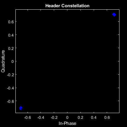
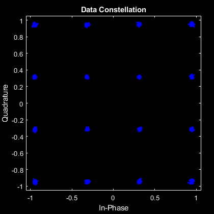
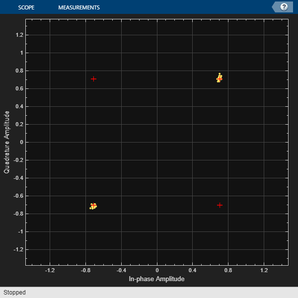
fprintf('\n Receiving process started...\n');
[rxDataBits,rxMatDiag] = whdlexamples.OFDMRx(double(fi(rxWaveform,1,16,14)));
fprintf('\n Reception completed\n\n');

% Plot constellation of header and data
scatterplot(rxMatDiag.matHeaderConstellation(:),1,0,'b.')
title('Header Constellation')
axisObj = gca;
axisObj.XColor = 'w';
axisObj.YColor = 'w';

scatterplot(rxMatDiag.matDataConstellation(:),1,0,'b.')
title('Data Constellation');
axisObj = gca;
axisObj.XColor = 'w';
axisObj.YColor = 'w';
 Receiving process started...

 Estimating carrier frequency offset ...

 First four frames are used for carrier frequency offset estimation.

 Estimated carrier frequency offset is 5.101999e-01 Hz.

 Detected and processing frame 5
------------------------------------------

 Header CRC passed

 Modulation: 16QAM, codeRate=1/2 and FFT Length=128

 Data CRC passed

 Data decoding completed
------------------------------------------

 Reception completed
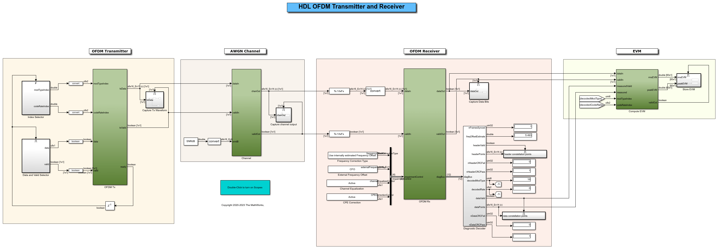
Verify Simulink Model with MATLAB Reference
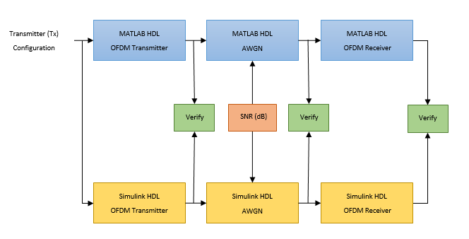
In this section, the Simulink HDL OFDM Transmitter, AWGN generator, and Simulink HDL OFDM Receiver implemented in fixed point are compared with the equivalent MATLAB HDL reference models implemented in floating point.
The Simulink model consists of an OFDM Transmitter that generates a time-domain waveform for a user-defined modulation order and code rate. The time-domain waveform is then passed through the AWGN channel that introduces AWGN noise of the desired SNR in dB. Then, the OFDM Receiver is used to demodulate and decode information bits. The outputs of the Simulink model are verified with the MATLAB reference at each stage.
open HDLOFDMTxRx;
simDiagnostics = sim("HDLOFDMTxRx");
### Searching for referenced models in model 'HDLOFDMTxRx'.
### Found 2 model reference targets to update.
### Starting serial model reference simulation build.
### Successfully updated the model reference simulation target for: whdlOFDMRx
### Successfully updated the model reference simulation target for: whdlOFDMTx

Build Summary

Model reference simulation targets:

Model       Build Reason                                   Status                        Build Duration
=======================================================================================================
whdlOFDMRx  Target (whdlOFDMRx_msf.mexw64) did not exist.  Code generated and compiled.  0h 9m 42.063s
whdlOFDMTx  Target (whdlOFDMTx_msf.mexw64) did not exist.  Code generated and compiled.  0h 6m 1.3838s

2 of 2 models built (0 models already up to date)
Build duration: 0h 16m 35.413s
Verify Simulink HDL OFDM Transmitter with MATLAB HDL OFDM Transmitter
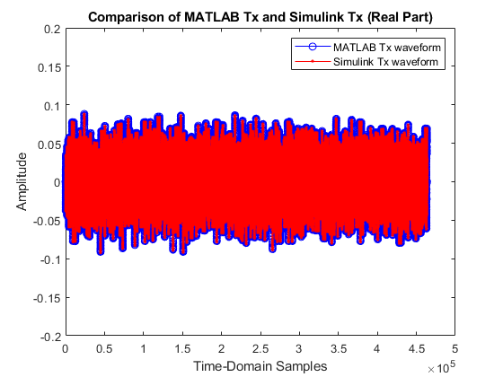
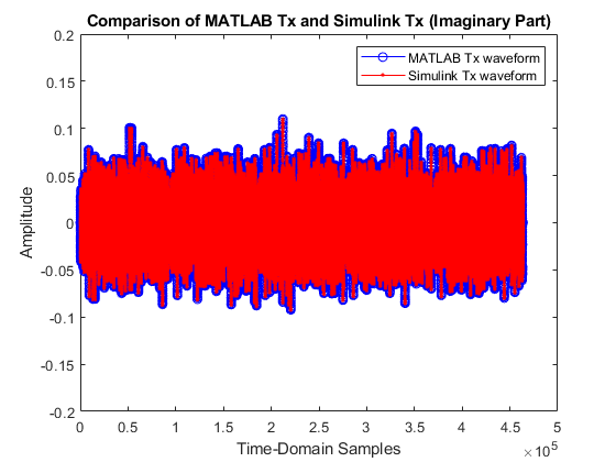
In this section, plot the real and imaginary parts of the HDL OFDM Transmitter MATLAB reference function output txWaveform and compare with the output of the HDL OFDM Transmitter block.
matlabTxWaveform = txWaveform;
simulinkTxWaveform = simDiagnostics.simTxOut;

figure;
plot(real(matlabTxWaveform),'-bo')
hold on
plot(real(simulinkTxWaveform(1:length(matlabTxWaveform))),'-r.')
legend('MATLAB Tx waveform','Simulink Tx waveform');
title('Comparison of MATLAB Tx and Simulink Tx (Real Part)');
ylim([-0.2 0.2]);
xlabel('Time-Domain Samples');
ylabel('Amplitude');

figure;
plot(imag(matlabTxWaveform),'-bo')
hold on
plot(imag(simulinkTxWaveform(1:length(matlabTxWaveform))),'-r.')
legend('MATLAB Tx waveform','Simulink Tx waveform');
title('Comparison of MATLAB Tx and Simulink Tx (Imaginary Part)');
ylim([-0.2 0.2]);
xlabel('Time-Domain Samples');
ylabel('Amplitude');
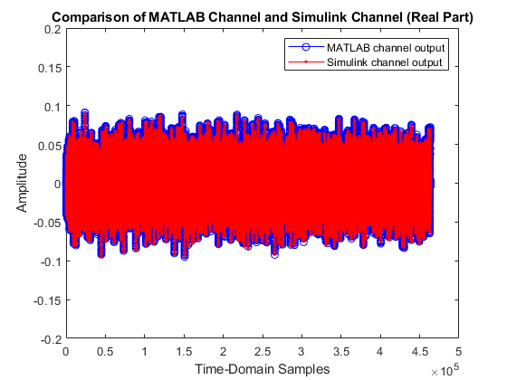
Verify Simulink HDL AWGN Generator with MATLAB HDL AWGN
In this section, plot the real and imaginary parts of the MATLAB HDL AWGN is compared with the output of the Simulink AWGN Generator block.
matlabChannelOut= rxWaveform;
simulinkChannelOut = simDiagnostics.simChannelOut;

figure;
plot(real(matlabChannelOut),'-bo');
hold on;
plot(real(simulinkChannelOut(1:length(matlabChannelOut))),'-r.');
legend('MATLAB channel output','Simulink channel output');
title('Comparison of MATLAB Channel and Simulink Channel (Real Part)');
ylim([-0.2 0.2]);
xlabel('Time-Domain Samples');
ylabel('Amplitude');

figure;
plot(imag(matlabChannelOut),'-bo');
hold on;
plot(imag(simulinkChannelOut(1:length(matlabChannelOut))),'-r.');
legend('MATLAB channel output','Simulink channel output');
title('Comparison of MATLAB Channel and Simulink Channel (Imaginary Part)');
ylim([-0.2 0.2]);
xlabel('Time-Domain Samples');
ylabel('Amplitude');

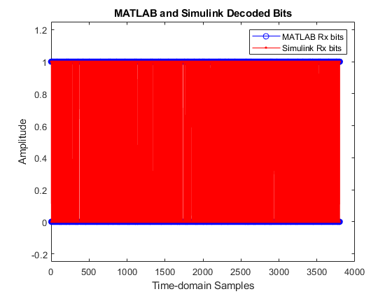
Verify Simulink HDL OFDM Receiver with MATLAB HDL OFDM Receiver
In this section, plot the decoded bits of the MATLAB receiver as compared with the decoded bits of the Simulink receiver.
matlabRxOut = rxDataBits;
simulinkRxOut = simDiagnostics.simRxDataBits;

figure;
plot(rxDataBits,'-bo');
hold on;
plot(simulinkRxOut(1:length(rxDataBits)),'-r.');
legend('MATLAB Rx bits','Simulink Rx bits');
title('MATLAB and Simulink Decoded Bits');
ylim([-0.25 1.25]);
xlabel('Time-domain Samples');
ylabel('Amplitude');
EVM Measurement
This section explains how to compute EVM at the output of OFDM Receiver using the EVM subsystem in the HDLOFDMTxRx model. In this model, the output of OFDM Receiver is connected to the Compute EVM subsystem. The Compute EVM subsystem accepts measured data constellation symbols, and the decoded data bits from the OFDM Receiver. The data bits are then processed using the transmitter data chain to generate the reference data constellation symbols.
EVM Subsystem
The Compute EVM subsystem contains the EVM subsystem that computes EVM using the measured and reference constellation symbols. The measured and reference symbols must be column vectors or scalars. You can select the following EVM types from the subsystem mask:
Base EVM — Computes root mean square (RMS) EVM and peak EVM of the input measured symbols in the current time step.
Base EVM and average of Base EVM — Computes Base EVM in the current time step and also the RMS average and peak of Base EVM values in consecutive time steps. You can specify the number of Base EVM values to average using the Averaging length of Base EVM parameter on the subsystem mask. To compute multiple averages of Base EVM, specify the averaging length as a column vector.
Subcarrier EVM — Computes RMS EVM and peak EVM per subcarrier of a multicarrier system, such as OFDM. Selecting this option enables the input ctrl port and the Number of subcarriers parameter. So, you have to provide the control signal that specifies the start and end of the OFDM frame and specify the number of subcarriers on the subsystem mask. You must provide all subcarriers of an OFDM symbol in a single clock as input measured symbols. The measured and reference input symbols must be of the same length as the number of subcarriers. The subsystem outputs the computed EVM at the end of the input frame.
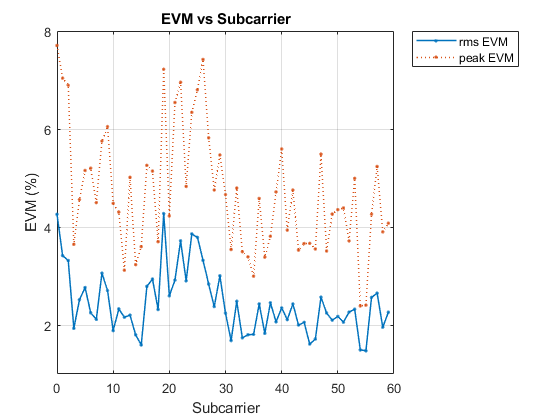
In the model, the EVM type parameter is set to Subcarrier EVM. After simulation, you can access the computed EVM values rmsEVM and peakEVM stored in the MATLAB workspace. The following figure shows the plot of rmsEVM and peakEVM values against OFDM subcarriers.
scIdx = 0:(dataPerSym-1);
figure; plot(scIdx,simDiagnostics.rmsEVM,'.-','LineWidth',1.1);
hold on; plot(scIdx,simDiagnostics.peakEVM,'.:','LineWidth',1.1);
title('EVM vs Subcarrier');
grid on;
xlabel('Subcarrier');
ylabel('EVM (%)');
legend('rms EVM','peak EVM','Location','bestoutside')
yLim = max(simDiagnostics.peakEVM)*1.1;
yTickStep = floor(yLim/3);
yticks(0:yTickStep:yLim)