
adc-synchronized-with-pwm

ADC synchronized with PWM
Copyright 2021 - 2022 The MathWorks, Inc.
Version
Main Branch: R2021b
R2019b Branch: R2019b
EN Introduction
This demo model shows how to control the current flowing in an inductor by changing the average voltage applied to the inductor by PWM.
How to Run
1.Open the Project file in this repoitry and open one of the models stored in the Models folder. 2.Run the simulation and check the waveforms in the Data Inspector or Scope Block.
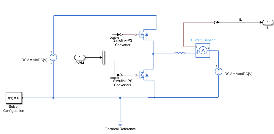

The current flowing in the inductor changes nonlinearly with PWM, and to control the current, it is necessary to obtain the average current in the PWM cycle. This model can be described in terms of two elements.
1.ADC execution synchronized with PWM timer
In order to obtain the average current, it is common to perform analog-to-digital conversion synchronized with a timer counter used to generate the pulse width. This Demo shows an example of performing AD conversion synchronized with a timer counter, i.e. PWM.
This method of implementation is well known to engineers who control motors, battery current control, and grid-connected inverter control design. Although there are many books that describe this method1.
2.Assign Dead Time
The model can also be given a DeadTime in the PWM generator. DeadTimes are inserted to avoid short-circuiting the device, but inserting DeadTimes introduces errors that can cause problems with convergence of the control response2. This model is also effective in such cases.
JP Introduction
PWMによってインダクタに印加する平均電圧を変更することで インダクタに流れる電流をコントロールを実施するDemoモデルです。
How to Run
1.このリポイトリのProjectファイルを開いて、Modelsフォルダに保存されているモデルのいずれかを開きます。 2.シミュレーションを実行してデータインスペクターで波形を確認します。
このモデルは2つの要素について説明できます
1.PWMタイマと同期したADC実行
平均電流を取得するにはパルス幅を生成する際に用いられるタイマカウンタに同期したアナログ・デジタル変換を実施することが一般的です。 このDemoではタイマカウンタ、すなわちPWMと同期したAD変換実行の例を示します。
このような実装方法は、モータ制御を行うエンジニアや、バッテリーの電流制御、系統連系インバーターの制御設計ではよく知られた手法です1。
2.DeadTimeの付与
このモデルはPWM生成部にてDeadTimeを付与することができます。 DeadTimeはデバイスの短絡を回避するために挿入されれますが、DeadTimeを挿入することで誤差が発生するため2、制御応答の収束性に課題が発生する場合があります。 そのような検討をを行う場合においても本モデルは有効です。
Required Toolboxes
MATLAB®/ Simulink®/ Simscape™/ Simscape Electrical™/ DSP System Toolbox™
Recomend Toolbox
Control System Toolbox™
モデルの伝達関数を表示するのに必要です。 SycnADC_WithFBParam.mの13行目以降をコメントアウトすればこのToolboxがなくてもモデルは動作します。
It is needed to display the transfer function of the model. If you comment out line 13 onwards of SycnADC_WithFBParam.m The model will work without this Toolbox.
Reference
Footnotes
-
Ricardo P. Aguilera et al. (2018). Digital Implementation of PI and Resonant Controller. In FREDE BLAABJERG(Eds.) CONTROL OF POWER ELECTRONIC CONVERTERS AND SYSTEMS volume1. Academic Press, pp.56-61 ↩ ↩2
-
Dead-time Voltage Error Correction with Parallel Disturbance Observers for High Performance V/f Control http://itohserver01.nagaokaut.ac.jp/itohlab/paper/2007/IAS2007/hoshino.pdf ↩ ↩2
Cite As
Yuki Kamatani (2024). adc-synchronized-with-pwm (https://github.com/mathworks/adc-synchronized-with-pwm/releases/tag/1.0.2), GitHub. Retrieved .
MATLAB Release Compatibility
Platform Compatibility
Windows macOS LinuxTags
Communities
Community Treasure Hunt
Find the treasures in MATLAB Central and discover how the community can help you!
Start Hunting!Discover Live Editor
Create scripts with code, output, and formatted text in a single executable document.
Parameters
Models
| Version | Published | Release Notes | |
|---|---|---|---|
| 1.0.2 | See release notes for this release on GitHub: https://github.com/mathworks/adc-synchronized-with-pwm/releases/tag/1.0.2 |
||
| 1.0.1 | See release notes for this release on GitHub: https://github.com/mathworks/adc-synchronized-with-pwm/releases/tag/1.0.1 |
||
| 1.0.0 |
You can also select a web site from the following list
Americas
- América Latina (Español)
- Canada (English)
- United States (English)
Europe
- Belgium (English)
- Denmark (English)
- Deutschland (Deutsch)
- España (Español)
- Finland (English)
- France (Français)
- Ireland (English)
- Italia (Italiano)
- Luxembourg (English)
- Netherlands (English)
- Norway (English)
- Österreich (Deutsch)
- Portugal (English)
- Sweden (English)
- Switzerland
- United Kingdom (English)
Asia Pacific
- Australia (English)
- India (English)
- New Zealand (English)
- 中国
- 日本Japanese (日本語)
- 한국Korean (한국어)