Adjacent and Co-Channel Interference
This model uses PSK-modulated signals to show the effects of adjacent and co-channel interference on a transmitted signal. You can view the effect of adjacent channel interferer and co-channel interferer together or individually.
Exploring the Example
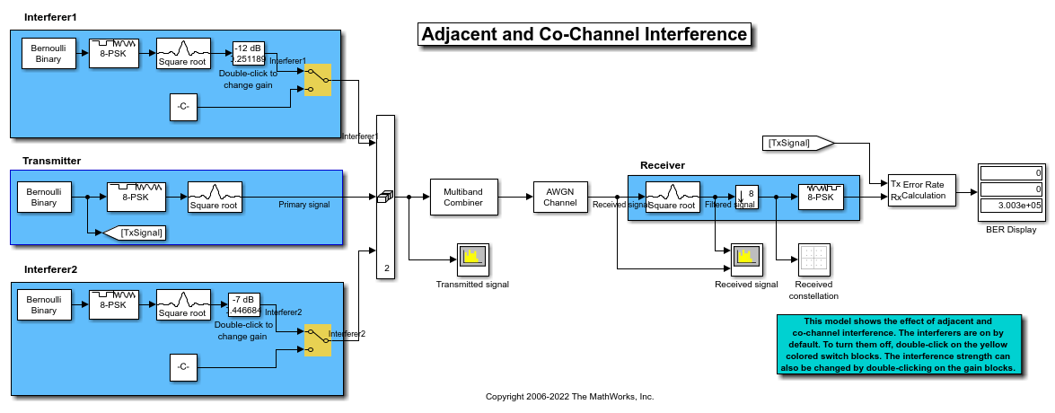
The communication system in this example includes these components:
Transmitter - Creates a PSK-modulated signal and applies a square root raised cosine filter. The interference is added to this Primary signal.
Interferer1 - Creates a PSK-modulated interference signal.
Interferer2 - Creates a PSK-modulated interference signal.
Multiband Combiner - Combines all the signals without introducing signal distortion and enables interference modeling. The Multiband Combiner block interpolates input signals, frequency shifts the signals by the value specified in the "Frequency offsets" parameter, and then combines the signals into one output signal.
AWGN Channel - Adds noise to the transmitted signals.
Receiver - Filters, downsamples, and demodulates the received signal.
Error Rate Calculation - Computes the bit error rate.
Results and Displays
When you run the simulation, the block labeled BER Display shows the bit error rate for the original signal. The BER Display block shows a three-element vector containing the calculated bit error rate (BER), the number of errors observed, and the number of bits processed.
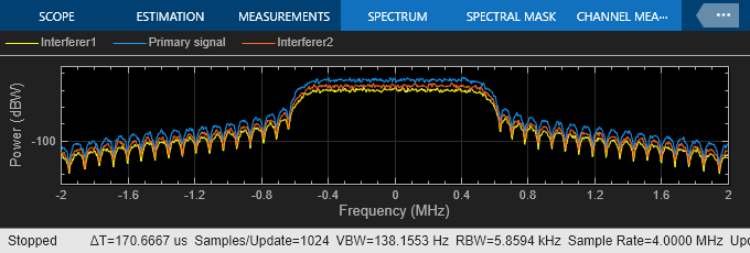
Scope blocks in the model display the spectra of the primary and interfering signals, spectrum of the received combined signal, and constellation diagram of the received signal.
The spectra of the primary and interfering signals. The corresponding systems generate these signals at baseband. Their relative spacing in the frequency domain and resulting interference is modeled by the Multiband Combiner block.
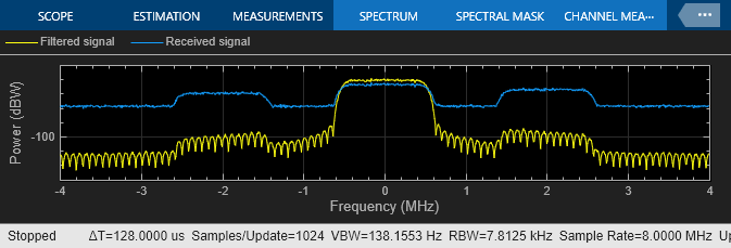
The spectrum of the received and filtered signals. The lowpass Raised Cosine Receive Filter block filters out interfering signals.
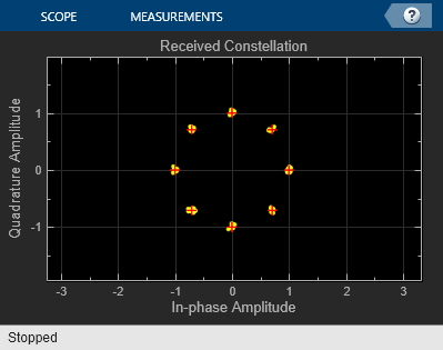
A scatter plot of the received signal, after it is filtered to recover the primary signal.
Experimenting with the Example
To deactivate an interferer, double-click the switch block that corresponds to that interferer. In the "Received signal" spectrum analyzer, notice the effect of omitting the interfering signal.
To change the spectral overlap between primary signal and interfering signals, set the "Frequency offsets" parameter of Multiband Combiner block. As you decrease the offset, the "Received signal" spectrum analyzer shows the interfering signal slowly moving from the adjacent channel into the frequency band of the original signal and eventually causing co-channel interference. The values reported in the BER Display block slowly deteriorate as the offset decreases, because the 8-PSK constellation points become difficult to demodulate correctly.
To change the power gain of an interfering signal, double-click the dB Gain block and change the Gain parameter. Observe the effect on the "Transmitted signal" and the "Received signal" spectrum analyzers. If you decrease the negative dB gain, the BER worsens, especially in the presence of co-channel interference.