RF Satellite Link
This model shows a satellite link, using the blocks from the Communications Toolbox™ to simulate the following impairments:
Memoryless nonlinearity
Free space path loss
Doppler error
Receiver thermal noise
Phase noise
In-phase and quadrature imbalances
DC offsets
The model optionally corrects most of these impairments.
By modeling the gains and losses on the link, this model implements link budget calculations that determine whether a downlink can be closed with a given bit error rate (BER). The gain and loss blocks, including the Free Space Path Loss block and the Receiver Thermal Noise block, determine the data rate that can be supported on the link in an additive white Gaussian noise channel.
Structure of the Example
The example highlights both the satellite link model and its signal scopes. The model consists of a Satellite Downlink Transmitter, Downlink Path, and Ground Station Downlink Receiver.
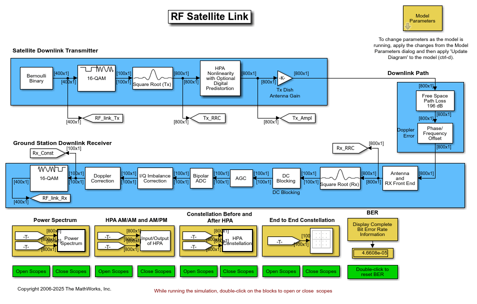
The blocks that correspond to each of these sections are
Satellite Downlink Transmitter
Bernoulli Binary Generator - Creates a random binary data stream.
Rectangular QAM Modulator Baseband - Maps the data stream to 16-QAM constellation.
Raised Cosine Transmit Filter - Upsamples and shapes the modulated signal using the square root raised cosine pulse shape.
HPA Nonlinearity with Optional Digital Predistortion(High Power Amplifier) - Models a traveling wave tube amplifier (TWTA) using the Saleh model option of the Memoryless Nonlinearity and optionally corrects the AM/AM and AM/PM with a Digital Predistortion block.Gain(Tx Dish Antenna Gain) - Applies gain of the transmitter parabolic dish antenna.
Downlink Path
Free Space Path Loss (Downlink Path) - Attenuates the signal by the free space path loss.
Phase/Frequency Offset (Doppler Error) - Rotates the signal to model Doppler error on the link.
Ground Station Downlink Receiver
Gain(Rx Dish Antenna Gain) - Applies gain of the receiver parabolic dish antenna.Receiver Thermal Noise (Satellite Receiver System Temp) - Adds white Gaussian noise that represents the effective system temperature of the receiver.
Phase Noise - Introduces random phase perturbations that result from 1/f or phase flicker noise.
I/Q Imbalance - Introduces DC offset, amplitude imbalance, or phase imbalance to the signal.
LNA(Low Noise Amplifier)- Applies low noise amplifier gain.Raised Cosine Receive Filter - Applies a matched filter to the modulated signal using the square root raised cosine pulse shape.
DC Blocker - Compensates for the DC offset in the I/Q Imbalance block.
AGC - Sets the signal power to a desired level.
I/Q Imbalance Compensator - Estimates and removes I/Q imbalance from the signal by a blind adaptive algorithm.
Doppler Correction- Uses the Carrier Synchronizer block to compensate for the carrier frequency offset due to Doppler.Rectangular QAM Demodulator Baseband - Demaps the data stream from the 16-QAM constellation space.
Exploring the Example
Double-click the block labeled Model Parameters to view the parameter settings for the model. All these parameters are tunable. To make changes to the parameters as the model is running, apply them in the dialog, then update the model via ctrl+d. The parameters are:
Satellite altitude (km) - Distance between the satellite and the ground station. Changing this parameter updates the Free Space Path Loss block. The default setting is 35600.
Frequency (MHz) - Carrier frequency of the link. Changing this parameter updates the Free Space Path Loss block. The default setting is 4000.
Transmit and receive antenna diameters (m) - The first element in the vector represents the transmit antenna diameter and is used to calculate the gain in the Tx Dish Antenna Gain block. The second element represents the receive antenna diameter and is used to calculate the gain in the Rx Dish Antenna Gain block. The default setting is [.4 .4].
Noise temperature (K) - Allows you to select from four effective receiver system noise temperatures. The selected noise temperature changes the Noise Temperature of the Receiver Thermal Noise block. The default setting is 20 K. The choices are
0 (no noise)- Use this setting to view the other RF impairments without the perturbing effects of noise.20 (very low noise level)- Use this setting to view how easily a low level of noise can, when combined with other RF impairments, degrade the performance of the link.290 (typical noise level)- Use this setting to view how a typical quiet satellite receiver operates.500 (high noise level)- Use this setting to view the receiver behavior when the system noise figure is 2.4 dB and the antenna noise temperature is 290K.
HPA backoff level - Allows you to select from three backoff levels. This parameter is used to determine how close the satellite high power amplifier is driven to saturation. The selected backoff is used to set the input and output gain of the Memoryless Nonlinearity block. The default setting is 30 dB (negligible nonlinearity). The choices are
30 dB (negligible nonlinearity)- Sets the average input power to 30 decibels below the input power that causes amplifier saturation (that is, the point at which the gain curve becomes flat). This causes negligible AM-to-AM and AM-to-PM conversion. AM-to-AM conversion is an indication of how the amplitude nonlinearity varies with the signal magnitude. AM-to-PM conversion is a measure of how the phase nonlinearity varies with signal magnitude.7 dB (moderate nonlinearity)- Sets the average input power to 7 decibels below the input power that causes amplifier saturation. This causes moderate AM-to-AM and AM-to-PM conversion, which is correctable with digital predistortion.1 dB (severe nonlinearity)- Sets the average input power to 1 decibel below the input power that causes amplifier saturation. This causes severe AM-to-AM and AM-to-PM conversion, and is not correctable with digital predistortion.
Doppler error - Allows you to select one of two values of Doppler. The selection updates the Phase/Frequency Offset (Doppler Error) block. The default setting is 0 Hz. The choices are
0 Hz- No Doppler on the link.3 Hz- Adds 3 Hz carrier frequency offset.
Phase noise - Allows you to select from three values of phase noise at the receiver. The selection updates the Phase Noise block. The default setting is Negligible (-100 dBc/Hz @ 100 Hz). The choices are
Negligible (-100 dBc/Hz @ 100 Hz)- Almost no phase noise.Low (-55 dBc/Hz @ 100 Hz)- Enough phase noise to be visible in both the spectral and I/Q domains, and cause bit errors when combined with thermal noise or other RF impairments.High (-48 dBc/Hz @ 100 Hz)- Enough phase noise to cause errors without the addition of thermal noise or other RF impairments.
I/Q imbalance and DC offset - Allows you to select from five types of in-phase and quadrature imbalances at the receiver. The selection updates the I/Q Imbalance block. The default setting is None. The choices are
None- No imbalances.Amplitude imbalance (3 dB)- Applies a 1.5 dB gain to the in-phase signal and a -1.5 dB gain to the quadrature signal.Phase imbalance (20 deg)- Rotates the in-phase signal by 10 degrees and the quadrature signal by -10 degrees.In-phase DC offset (1e-8)- Adds a DC offset of 1e-8 to the in-phase signal amplitude. This offset changes the received signal constellation diagram, but does not cause errors on the link unless combined with thermal noise or other RF impairments.Quadrature DC offset (5e-8)- Adds a DC offset of 5e-8 to the quadrature signal amplitude. This offset causes errors on the link even when not combined with thermal noise or another RF impairment. This offset also causes a DC spike in the received signal spectrum.
Digital predistortion - Allows you to enable or disable the Digital Predistortion subsystem. The default setting is Disabled.
DC offset correction - Allows you to enable or disable the DC Blocking subsystem. The default setting is Disabled.
Doppler correction - Allows you to enable or disable the Doppler Correction subsystem. The default setting is Disabled.
I/Q imbalance correction - Allows you to enable or disable the I/Q Imbalance Correction subsystem. The default setting is Disabled.
Results and Displays
When you run this model, the following displays are active:
Power Spectrum - Double-clicking this Open Scopes block enables you to view the spectrum of the modulated/filtered signal (yellow) and the received signal before demodulation (blue).
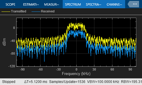
Comparing the two spectra allows you to view the effect of the following RF impairments:
Spectral regrowth due to HPA nonlinearities caused by the Memoryless Nonlinearity block
Thermal noise caused by the Receiver Thermal Noise block
Phase flicker (that is, 1/f noise) caused by the Phase Noise block
HPA AM/AM and AM/PM - Double-clicking this Open Scopes block enables you to view the AM/AM and AM/PM conversion after the HPA. These plots enable you to view the impact that the Digital Predistortion block and HPA have on the linearity of the signal.
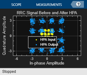
Constellation Before and After HPA - Double-clicking this Open Scopes block enables you to compare the constellation of the transmitted signal before (yellow) and after (blue) the HPA. The amplifier gain causes the HPA Output signal to be larger than the HPA Input signal. This plot enables you to view the combined effect of both the HPA nonlinearity and digital predistortion.
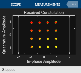
End to End Constellation - Double-clicking this Open Scopes block enables you to compare the reference 16-QAM constellation (red) with the received QAM constellation before demodulation (yellow). Comparing these constellation diagrams allows you to view the impact of all the RF impairments on the received signal and the effectiveness of the compensations.
Bit error rate (BER) display - In the lower right corner of the model is a display of the BER of the model. The BER computation can be reset manually by double-clicking the green "Double-click to reset BER" button. This allows you to view the impact of the parameter changes as the model is running.
Experimenting with the Example
This section describes some ways that you can change the model parameters to experiment with the effects of the blocks from the RF Impairments library and other blocks in the model. You can double-click the block labeled "Model Parameters" in the model and try some of the following scenarios:
Link gains and losses - Change Noise temperature to 290 (typical noise level), 0 (no noise) or 500 (high noise level). Change the value of the Satellite altitude (km) or Satellite frequency (MHz) parameters to change the free space path loss. In addition, increase or decrease the Transmit and receive antenna diameters (m) parameter to increase or decrease the received signal power. You can view the changes in the received constellation in the received signal constellation diagram scope and the changes in received power in the spectrum analyzer.
Raised cosine pulse shaping - Make sure Noise temperature is set to 0 (no noise). Turn on the Constellation Before and After HPA scopes. Observe that the square-root raised cosine filtering results in intersymbol interference (ISI). This results in the points being scattered loosely around ideal constellation points, which you can see in the After HPA constellation diagram. The square-root raised cosine filter in the receiver, in conjunction with the transmit filter, controls the ISI, which you can see in the received signal constellation diagram.
HPA AM-to-AM conversion and AM-to-PM conversion - Change the HPA backoff level parameter to 7 dB (moderate nonlinearity) and observe the AM-to-AM and AM-to-PM conversions by comparing the Transmit RRC filtered signal constellation diagram with the RRC signal after HPA constellation diagram. Note how the AM-to-AM conversion varies according to the different signal amplitudes. You can also view the effect of this conversion on the received signal in the received signal constellation diagram. In addition, you can observe the spectral regrowth in the received signal spectrum analyzer. You can also view the phase change in the received signal in the received signal constellation diagram scope.
Digital predistortion With the Digital predistortion checkbox checked, change the HPA backoff level parameter to 30 dB (negligible nonlinearity), 7 dB (moderate nonlinearity), and 1 dB (severe nonlinearity) to view the effect of digital predistortion on the HPA nonlinearity.
Phase noise plus AM-to-AM conversion - Set the Phase Noise parameter to High and observe the increased variance in the tangential direction in the received signal constellation diagram. Also note that this level of phase noise is sufficient to cause errors in an otherwise error-free channel.
DC offset and DC offset compensation - Set the I/Q imbalance and DC offset parameter to In-phase DC offset (1e-8) and view the shift of the constellation in the received signal constellation diagram. Set DC offset correction to Enabled and view the received signal constellation diagram to view how the DC offset block estimates the DC offset value and removes it from the signal. Set DC offset compensation to Disabled and change I/Q imbalance to Quadrature DC offset (5e-8). View the changes in the received signal constellation diagram for a large DC offset and the DC spike in the received signal spectrum. Note that the LNA amplifies the small DC offsets so that they are visible on the constellation diagram with much larger axis limits. Set DC offset compensation to Enabled and view the received signal constellation diagram and spectrum analyzer to see how the DC component is removed.
Amplitude imbalance - With the I/Q imbalance correction disabled, set the I/Q Imbalance and DC offset parameter to Amplitude imbalance (3 dB) to view the effect of unbalanced I and Q gains in the received signal constellation diagram. Enable the I/Q imbalance correction to compensate for the amplitude imbalance.
Doppler and Doppler compensation - Disable Doppler correction by unchecking the Doppler correction check box. Set Doppler error to 3 Hz to show the effect of uncorrected Doppler on the received signal constellation diagram. Enable Doppler correction to show that the carrier synchronizer restores the received constellation. Repeat the exercise with different I/Q imbalance and DC offsets.
Selected Bibliography
[1] Saleh, Adel A.M., "Frequency-Independent and Frequency-Dependent Nonlinear Models of TWT Amplifiers," IEEE® Transactions on Communications, Vol. COM-29, No. 11, November 1981.
[2] Kasdin, N.J., "Discrete Simulation of Colored Noise and Stochastic Processes and 1/(f^alpha); Power Law Noise Generation," The Proceedings of the IEEE, Vol. 83, No. 5, May, 1995.
[3] Kasdin, N. Jeremy, and Todd Walter, "Discrete Simulation of Power Law Noise," 1992 IEEE Frequency Control Symposium.
[4] Sklar, Bernard, Digital Communications: Fundamentals and Applications, Englewood Cliffs, N.J., Prentice Hall, 1988.