Raised Cosine Transmit Filter
Apply pulse shaping by interpolating signal using raised cosine FIR filter
Libraries:
Communications Toolbox /
Comm Filters
Communications Toolbox HDL Support /
Comm Filters
Description
The Raised Cosine Transmit Filter block applies pulse shaping by interpolating an input signal using a raised cosine finite impulse response (FIR) filter. The FIR filter has (Filter span in symbols × Output samples per symbol + 1) tap coefficients. The block icon shows the impulse response of the filter. For more information, see Algorithms.
Examples
The Raised Cosine Transmit Filter and Raised Cosine Receive Filter blocks are designed for raised cosine (RC) filtering. Each block can apply a square-root raised cosine (RRC) filter or a raised cosine filter to a signal. You can vary the roll-off factor and span of the filter.
The Raised Cosine Transmit Filter and Raised Cosine Receive Filter blocks are tailored for use at the transmitter and receiver, respectively. The transmit filter upsamples (interpolates) the output signal. The receive filter expects its input signal to be upsampled and downsamples (decimates) the output signal, based on the configured settings of the block.
The raised cosine transmit and receive filter blocks each introduce a propagation delay, as described in Group Delay.
The doc_rrcfiltercompare.slx model shows how to split the filtering equally between the transmitter and the receiver by using a pair of square root raised cosine filters. The use of a matched pair of square root raised cosine filters is equivalent to a single normal raised cosine filter. The filters share the same span and use the same number samples per symbol but the two filter blocks on the upper path have a square root shape and the single filter block on the lower path has the normal shape.

Run the model and observe the eye and constellation diagrams. The performance is nearly identical for the two methods. Note that the limited impulse response of practical square root raised cosine filters causes a slight difference between the response of two cascaded square root raised cosine filters and the response of one raised cosine filter.


Apply root raised cosine filtering to a QPSK-modulated signal. Compute the variance of the filtered signal. Plot the signal before and after filtering.
In the cm_tx_rrc_filter model, a binary is QPSK modulated and then root raised cosine filtered with the oversampling rate set to 8 and the roll-off factor set to 0.2.
![]()
The signal level reduces by a factor of one over the oversample rate. Since the QPSK-modulated signal has unity power and the transmit RRC filtering oversamples the signal by 8, the Variance block after the transmit filtering computes a variance level of approximately 1/8.
Computed variance = 0.1248
![]()
Apply raised cosine matched filtering to a modulated signal by applying transmit and receive root raised cosine (RRC) filtering to the input signal. Demonstrate input signal power adjustment for correct SNR and the delay adjustment for correct error rate calculation.
The cm_tx_rx_rrc_filter model outputs frames of random integers by using a Random Integer Generator block. The frames of data pass through a QPSK Modulator Baseband block, Raised Cosine Transmit Filter, AWGN Channel block, Raised Cosine Receive Filter, and QPSK Demodulator Baseband block. Separate Error Rate Calculation blocks compute the bit error rate after QPSK demodulation, with and without accounting for the delay of the received signal due to the transmit and receive filtering.
The model initializes the variables that configure block parameters by using the PreLoadFcn callback function. For more information, see Model Callbacks (Simulink). The model demonstrates configuration of parameters to set the input signal power level for AWGN based on filter oversampling, and to set the delay for the error rate calculation path based on the filter delay.

The QPSK-modulated signal has unity power, but signal oversampling by the transmit RRC filtering reduces the signal level by the oversampling rate. To apply the correct noise level, you must adjust the input signal power in the AWGN block to account for the reduced signal level due to oversampling by the filter. A Variance block computes a variance to be approximately one over the oversampling rate, 1/8.
Computed variance = 0.1250

A Time Scope plots the Received, Delayed, and Not delayed signals. The Delayed signal aligns with the Received signal, but the Not delayed signal is shifted by 10 samples. The error rate calculation shows the correct BER when you account for the filter delay.
 Delay not accounted for: BER = 0.75
 Delay accounted for:     BER = 0.00461
Extended Examples

Frame Synchronization Using Barker Code Preamble
Use a length 13 Barker code frame preamble for frame synchronization of data bits.
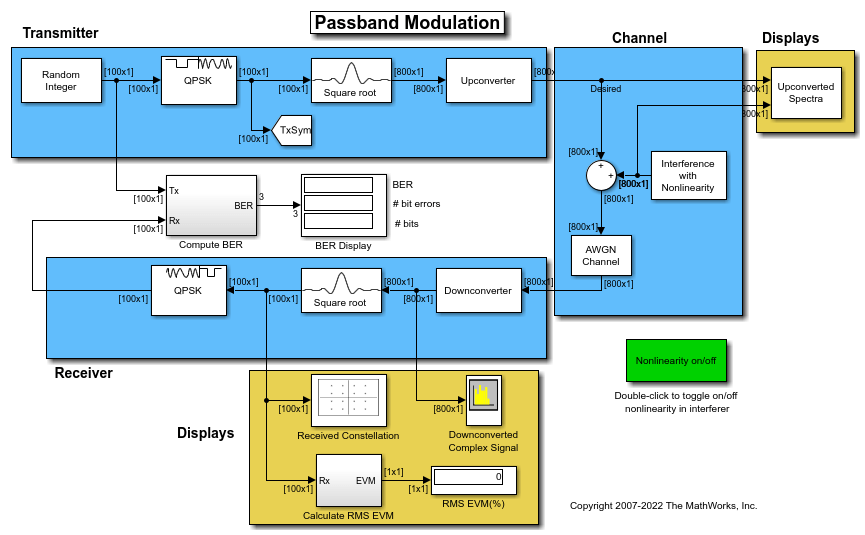
Passband Modulation
Simulate passband modulation by multiplying a modulated complex signal with a complex sine wave to perform frequency upconversion.
Ports
Input
Output
Parameters
Block Characteristics
More About
The Data Type Assistant helps you set data
attributes. To use the Data Type Assistant, click ![]() . For more information, see Specify Data Types Using Data Type Assistant (Simulink).
. For more information, see Specify Data Types Using Data Type Assistant (Simulink).
Tips
Exporting Filter Coefficients to the MATLAB Workspace
To examine or manipulate the coefficients of the filter that this block designs, select Export filter coefficients to workspace. Set the Coefficient variable name parameter to the name of a variable that you want the block to create in the MATLAB workspace. Running the simulation causes the block to create the variable, overwriting any previous contents in case the variable already exists.