Data Mapper
Map integer symbols from one coding scheme to another
Libraries:
Communications Toolbox /
Utility Blocks
Description
The Data Mapper block accepts integer inputs and maps them to integer outputs. The mapping types include: binary to Gray coded, Gray coded to binary, and user defined. Additionally, a pass through option is available.
Gray coding is an ordering of binary numbers such that all adjacent numbers differ by only one bit.
Examples
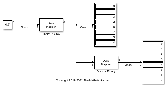
Binary to Gray Conversion in Simulink
The doc_binary2gray model converts a binary sequence to a Gray-coded sequence and vice versa by using Data Mapper blocks.
Run the model.
The Display blocks show the binary-coded and Gray-coded sequence ordering.
Ports
Input
Output
Parameters
Block Characteristics
Data Types |
|
Multidimensional Signals |
|
Variable-Size Signals |
|
Extended Capabilities
Version History
Introduced before R2006a
See Also
You can also select a web site from the following list:
Americas
- América Latina (Español)
- Canada (English)
- United States (English)
Europe
- Belgium (English)
- Denmark (English)
- Deutschland (Deutsch)
- España (Español)
- Finland (English)
- France (Français)
- Ireland (English)
- Italia (Italiano)
- Luxembourg (English)
- Netherlands (English)
- Norway (English)
- Österreich (Deutsch)
- Portugal (English)
- Sweden (English)
- Switzerland
- United Kingdom (English)