Bus Selector
Select elements from input bus
Libraries:
Simulink /
Commonly Used Blocks
Simulink /
Signal Routing
HDL Coder /
Signal Routing
Description
The Bus Selector block extracts the elements you select by name from the input bus hierarchy. The block can output the selected elements separately or in a new virtual bus. When the block outputs the selected elements separately, each selected element corresponds to an output port. When the block outputs a new virtual bus, the block has one output port for the virtual bus that contains each selected element.
While multiple elements can have the same name in different locations in the bus
hierarchy, each element has a unique fully qualified name that the Bus Selector
block uses. For example, the top-level bus and a nested bus can both have an element named
chirp. The fully qualified name for the element in the top-level bus is
chirp. The fully qualified name for the element in the nested bus is
nestedbus.chirp, where nestedbus is the name of the
nested bus.
Tip
For buses at subsystem and model interfaces, use In Bus Element blocks instead of an Inport block with a Bus Selector block. In Bus Element blocks:
Reduce line complexity and clutter in a block diagram.
Allow you to more easily change the interface incrementally.
Allow access to a bus element closer to the point of usage, avoiding the use of a Bus Selector and Goto block configuration.
Examples
The Bus Selector block lets you extract elements from a bus by name.
Open and compile the example model named BusElementSelection. To compile the model, on the Modeling tab of the Simulink® Toolstrip, click Update Model or Run. Compiling the model updates the line styles, which you can use to visually identify buses.
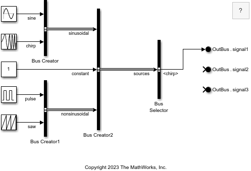
The Bus Creator blocks create a bus hierarchy from source signals.
The Bus Creator block named
Bus Creatorgroups the signals namedsineandchirpinto a bus namedsinusoidal.The Bus Creator block named
Bus Creator1groups the signals namedpulseandsawinto a bus namednonsinusoidal.The Bus Creator block named
Bus Creator2groups the two buses and the signal namedconstantinto a bus namedsources.
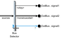
The Bus Selector block receives the bus named sources as input and returns the signal named chirp as output.
In this example, the Bus Selector block output connects to an Out Bus Element block. Two Out Bus Element blocks remain unconnected.
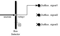
To add an output port to the Bus Selector block, click the output edge of the Bus Selector block.
Start typing the name of the element you want to select, for example, nonsinusoidal.
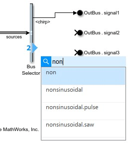
Use the arrow keys to select the element named nonsinusoidal. Then, press Enter. Alternatively, click the element name in the menu.
Connect the new port to an Out Bus Element block. Optionally, compile the model to display the bus line style for the selected bus.
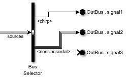
To connect a block to a new output port on the Bus Selector block, drag an unconnected input port of the block to the output edge of the Bus Selector block.
For example, drag the input port of the remaining Out Bus Element block to the output edge of the Bus Selector block.
Start typing the name of the element you want to select, for example, saw.
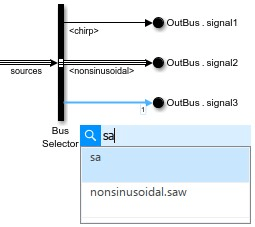
Use the arrow keys to select the element named nonsinusoidal.saw. Then, press Enter. Alternatively, click the element name in the menu.
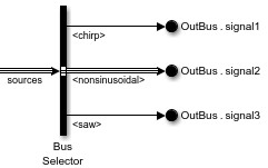
In this example, the fully qualified element name is nonsinusoidal.saw because the signal named saw is in the nested bus named nonsinusoidal.
While this example shows how to select elements from the input bus from the block diagram, you can also double-click the Bus Selector block and select output elements in the dialog box that opens.
Extended Examples

Simulink Bus Capabilities
Work with buses in components, simplify component interfaces, and streamline common bus workflows.
Ports
Input
Output
Parameters
To edit block parameters interactively, use the Property Inspector. From the Simulink® Toolstrip, on the Simulation tab, in the Prepare gallery, select Property Inspector.
By default, the Property Inspector uses a vertical layout, with the output
elements under the list of elements in the bus. To view the elements in the bus and the
output elements side by side, click ![]() .
.
This parameter is read-only.
The list of elements in the bus provides the elements that enter the block, including nested buses and their elements. An arrow next to an element indicates that an input element is a bus. To display the contents of that bus, click the arrow.
To filter the elements in the bus by name with or without regular
expression, enter the search term in the Filter box. Do
not enclose the search term in quotation marks. Optionally, display the
filtered results as a flat list by clicking ![]() . The flat list uses dot notation to
reflect the bus hierarchy. By default, the filtered results appear in a
hierarchical tree.
. The flat list uses dot notation to
reflect the bus hierarchy. By default, the filtered results appear in a
hierarchical tree.
To select the source of an element that enters the block, select the element in the list.
Then, click ![]() . Alternatively, right-click the element.
Then, select Select source blocks. The Property
Inspector shows the parameters of the selected source block. When
you select the source block of multiple elements, the Property
Inspector shows the parameters of the source block that has
focus.
. Alternatively, right-click the element.
Then, select Select source blocks. The Property
Inspector shows the parameters of the selected source block. When
you select the source block of multiple elements, the Property
Inspector shows the parameters of the source block that has
focus.
To refresh the list of elements that enter the block, click ![]() . For example, click this button when you
change an element name while the dialog box is open.
. For example, click this button when you
change an element name while the dialog box is open.
Tips
A green check mark icon appears next to selected output elements.
When you pause on a selected output element, a parenthetical displays how many times the Bus Selector block selects that element.
Regular expressions let you filter based on whether the input elements match a pattern. For example, enter
t$in the Filter box to display all elements whose names end with a lowercaset. For more informations, see Regular Expressions.
Programmatic Use
To get the block parameter value
programmatically, use the get_param function.
| Parameter: | InputSignals |
| Values: | Read-only: cell array of element names |
Example: get_param(gcb,'InputSignals')
The list of selected elements provides the elements that exit the block. The list uses the fully qualified name for each element.
In the Simulink Editor, when Output as virtual bus is cleared, select elements from the input bus by adding ports to the block.
Click the output edge of the Bus Selector block. Alternatively, when the block receives a bus and all output ports connect to other ports, draw a new line close to the output edge of the Bus Selector block.
Specify an element to select.
In the Property Inspector or Block Parameters dialog box, select elements from the input bus by adding elements to the Output elements list.
In the Elements in the bus list, select one or more elements that you want to add to the block output.
When you select multiple elements from the Elements in the bus list, the order in which you select them sets their order when you add them to the Output elements list.
Optionally, in the Output elements list, select the element that you want to add elements below. When you select no element, the software adds the elements at the end of the list.
Click
 or
or  , depending on the layout of
the dialog box. Alternatively, right-click one of the selected
elements. Then, click Add to
output.
, depending on the layout of
the dialog box. Alternatively, right-click one of the selected
elements. Then, click Add to
output.
To change the order of the output elements, drag elements in the Output elements list to a different position. Port connectivity is maintained when you change the element order.
To remove elements from the block output, select the elements to remove from the
Output elements list. Then, click ![]() . Alternatively, right-click one of the
selected elements. Then, select Remove.
. Alternatively, right-click one of the
selected elements. Then, select Remove.
If an element in the list is not in the input bus, the element name is red. Remove the element from the list of selected elements or modify the input bus to include an element with the specified name. To remove all output elements that are not in the input bus, right-click an element name that is red. Then, select Remove all invalid elements.
Programmatic Use
To set the block parameter value programmatically, use
the set_param function.
| Parameter: | OutputSignals |
| Values: | 'signal1,signal2' (default) | comma-separated list of element names in quotes |
| Data Types: | char | string |
Example: set_param(gcb,'OutputSignals','constant,sine')
By default, the block outputs each of the selected elements from a separate output port that is labeled with the corresponding bus element name. To output the selected elements from one port, grouped in a virtual bus, select this parameter.
To convert the output to a nonvirtual bus, insert a Signal Conversion block after the Bus Selector block. Set the
Signal Conversion block Output parameter to
Nonvirtual bus and set the Data type
to a Simulink.Bus object.
When the Output elements list includes only one element and you select this parameter, that element is not wrapped in a bus. For example, if the element is a bus, the output element is that bus. If the element is not a bus, the output element is not a bus.
Dependencies
To use this parameter, the block output must not include messages.
Programmatic Use
To set the block parameter value programmatically, use
the set_param function.
| Parameter: | OutputAsBus |
| Values: | 'off' (default) | 'on' |
Example: set_param(gcb,'OutputAsBus','on')
Block Characteristics
Data Types |
|
Direct Feedthrough |
|
Multidimensional Signals |
|
Variable-Size Signals |
|
Zero-Crossing Detection |
|
Tips
By default, the dialog box opens in a vertical layout, with the selected elements under the
list of elements in the bus. To view the elements in the bus and the selected output
elements side by side, click ![]() .
.
Extended Capabilities
Version History
Introduced before R2006aYou can now specify Bus Selector block parameters in the Property Inspector. When you make changes in the Property Inspector or Block Parameters dialog box, the changes apply immediately. The Apply and OK buttons have been removed.
The Bus Selector block must have at least one output element. To completely
replace the output elements, add elements from the input bus to the block output.
Then, remove the original output elements. For example, for a new Bus
Selector block, add elements from the input bus to the block output.
Then, right-click the placeholder element named signal1 and
select Remove all invalid elements.
When you find the source blocks of input elements, the source blocks are now selected
instead of highlighted. The Property Inspector shows the parameters of
the selected source block. When you select the source block of multiple elements,
the Property Inspector shows the parameters of the source block that
has focus. To reflect this change, the Highlight source
blocks option (![]() ) is now called Select source
blocks.
) is now called Select source
blocks.
When you interact with Bus Selector blocks, the results of your actions are more clear.
The Select elements button
is now the Add to output button
.The Selected elements list is now the Output elements list.
The Output as virtual bus button
 is now the Output as virtual
bus check box.
is now the Output as virtual
bus check box.
The Bus Selector block dialog box has a streamlined design with additional functionality.
In the Elements in the bus list, a green check mark icon appears next to selected output elements.
In the Elements in the bus list, when you pause on a selected output element, a parenthetical displays how many times the Bus Selector block selects that element.
Filtering supports regular expressions by default.
You can toggle between vertical and horizontal layouts.
The previous functionality remains.
By default, the dialog box opens in a vertical layout, with the selected elements
under the list of elements in the bus. To view the elements in the bus and the
selected output elements side by side, click ![]() .
.
The horizontal layout more closely mimics the previous Bus Selector block dialog box design.