Delay
Delay input signal by fixed or variable sample periods
Libraries:
Simulink /
Commonly Used Blocks
Simulink /
Discrete
DSP System Toolbox /
Signal Operations
HDL Coder /
Commonly Used Blocks
HDL Coder /
Discrete
Alternative Configurations of Delay Block:
Resettable Delay
Description
The Delay block outputs the input of the block after a delay. The block determines the delay time based on the value of the Delay length parameter. The block supports:
Variable delay length
Specification of the initial condition from an input port
State storage
Using a circular buffer instead of an array buffer for state storage
Resetting the state to the initial condition with an external reset signal
Controlling execution of the block at every time step with an external enable signal
The initial block output depends on several factors such as the Initial condition parameter and the simulation start time. For more information, see Initial Block Output. The External reset parameter determines if the block output resets to the initial condition on triggering. The Show enable port parameter determines if the block execution is controlled in every time step by an external enable signal.
Initial Block Output
The output in the first few time steps of the simulation depends on the block sample time, the delay length, and the simulation start time. The block supports specifying or inheriting discrete sample times to determine the time interval between samples. For more information, see Specify Sample Time.
The table shows the Delay block output for the first few time steps with these
settings. The block inherits a discrete sample time as
[,
where Tsampling,Toffset]TsamplingToffsetn is the value of the Delay
length parameter and
Tstart
| Simulation Time Range | Block Output |
|---|---|
| Zero |
| Initial condition parameter |
After | Input signal |
Behavior with External Enable Signal
Selecting the Show enable port check box enables the Enable port. If the enable port is enabled, the block operates in this order
Checks if the enable condition is satisfied.
If the reset port is enabled, checks the reset condition.
Performs the Delay block functionality.
The block has this operation with the Enable port:
At the first block enable, the block output is the initial condition value (
x0).For consecutive enable signals, the block takes the last state of the input signal u.
If the port is not enabled at the start of simulation, the Delay block outputs
0.During simulation, if the port becomes disabled after having been enabled, the block does not execute and holds its last value.
Variable-Size Support
The Delay block provides the following support for variable-size signals:
The data input port
uaccepts variable-size signals. The other input ports do not accept variable-size signals.The output port has the same signal dimensions as the data input port
ufor variable-size inputs.
The rules that apply to variable-size signals depend on the input processing mode of the Delay block.
| Input Processing Mode | Rules for Variable-Size Signal Support |
|---|---|
Elements as channels (sample based)
|
|
Columns
									as channels (frame based)
|
|
Bus Support
The Delay block provides the following support for bus signals:
The data input
uaccepts virtual and nonvirtual bus signals. Other than input portx0, the other input ports do not accept bus signals.The initial condition
x0port accepts nonvirtual bus signals.The output port has the same bus type as the data input port
ufor bus inputs.Buses work with:
Sample-based and frame-based processing
Fixed and variable delay length
Array and circular buffers
To use a bus signal as the input to a Delay block, specify the
initial condition on the dialog box or through the x0 port.
Support for virtual and nonvirtual buses depends on the initial condition that you
specify and whether the State name parameter is empty or not.
For the x0 input port, only nonvirtual buses are
supported.
| Initial Condition | State Name | |
|---|---|---|
| Empty | Not Empty | |
| Zero | Virtual and nonvirtual bus support | Nonvirtual bus support only |
| Nonzero scalar | Virtual and nonvirtual bus support | No bus support |
| Nonscalar | No bus support | No bus support |
| Structure | Virtual and nonvirtual bus support | Nonvirtual bus support only |
| Partial structure | Virtual and nonvirtual bus support | Nonvirtual bus support only |
String Support
The Delay block can accept and output string data type only if:
The block is configured for the default value of the Initial condition parameter (0).
The Delay length value is 1 or less.
Examples
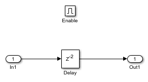
This example shows how the Delay block supports variable-size signals for sample-based processing. The Switch block controls whether the input signal to the enabled subsystem is a 3-by-3 or 3-by-2 matrix.
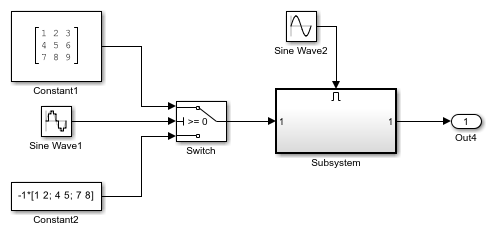
The Delay block appears inside the enabled subsystem.
The model follows these rules for variable-size signals while using sample-based processing.
Signal dimensions change only during state reset when the block is enabled.
Initial condition must be scalar.
The rules are implemented by these blocks.
Enable block sets Propagate sizes of variable-size signals to
Only when enabling.Delay block sets the Initial condition to the scalar value
0.0.
This example shows how the Delay block supports buses for frame-based processing.
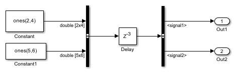
Each Constant block supplies an input signal to the Bus Creator block, which outputs a two-dimensional bus. After the Delay block delays the bus by three sample periods, the Bus Selector block separates the bus back into the two original signals.
The model follows these rules for buses:
For the initial condition, set the value on the dialog box.
For frame-based processing, signal dimensions of the data input port
ucannot be larger than two.
The model implements the rules by:
Setting Initial condition to a scalar value of
0.Setting bus input to the Delay block as two dimensions.
This example shows how you can enable or disable the execution of the Delay block using an enable port. In this model, a ramp input signal feeds into a Delay block. The execution of the block is controlled by an enabling signal from the Pulse Generator block.
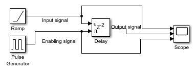
The blue line shows that the Delay block outputs the input signal value delayed by one time step while the enabling signal has a value of one. At t=5 the enabling signal transitions to zero and the Delay block stops executing. The output is held at the last value until the block is enabled again.