Highlight Signal Sources and Destinations
You can highlight a signal and its source or destination blocks in Simulink®, and then remove the highlighting when it is not required any more. Signal highlighting crosses subsystem and model reference boundaries, allowing you to trace a signal across multiple subsystem levels. If a signal is composite, all source or destination blocks are highlighted. For more information on composite signals, see Composite Interface Guidelines.
To continue the trace towards the source or destination of the signal, use the left and right arrow keys of your keyboard, respectively.
Highlight Signal Source
To begin a trace to the source blocks of a signal, right-click the signal line, and
then click the Trace to Source button ![]() . The
. The ![]() badge identifies the start of the trace. This option
highlights:
badge identifies the start of the trace. This option
highlights:
All branches of the signal anywhere in the model
All virtual blocks through which the signal passes
The nonvirtual blocks that write the value of the signal

To continue tracing towards the source of the signal, press the Left arrow key.
Highlight Signal Destination
To begin a trace to the destination blocks of a signal, right-click the signal line,
and then click the Trace to Destination button ![]() . Press the Right arrow key to move
the trace towards the final destination. The
. Press the Right arrow key to move
the trace towards the final destination. The ![]() badge identifies the start of the trace. This option
highlights:
badge identifies the start of the trace. This option
highlights:
All branches of the signal anywhere in the model
All virtual blocks through which the signal passes
The nonvirtual blocks that read the value of the signal
The signal and destination block for all blocks that are duplicates of the Inport block for the line that you select
In this example, the selected trace shows a path of the signal from the Stick
Input to the Elevator Command in the
Controller subsystem of the f14 model.

In the next example, right-clicking the signal from In2 and
clicking the Trace to Destination button ![]() highlights the signal and destination block for
highlights the signal and destination block for
In2 and In1, because In1
and In2 are duplicate Inport blocks.

Choose the Path of a Trace
In some situations, a signal trace can take multiple viable paths in the next segment of the trace. This can be seen when a signal is combined or split through a Mux or Demux block, or if it is branched out as an input to another block. In such cases, the options are highlighted in blue and can be cycled using the Up and Down arrow keys on the keyboard. Once you have highlighted the block to which you would like to move, proceed as normal.

In the figure above, the trace to source has reached the Sum block where it can take one of three possible paths. The first option to Gain Zd is highlighted in blue.
Trace a Signal to and from Subsystems
When the trace reaches a subsystem, it does not automatically trace in. Instead, the trace highlights the target subsystem and you are able to see a preview of the trace within the subsystem.
In this example, the selected signal trace to destination has reached the
Controller subsystem of the f14 model. You can see
that the contents of the subsystem are visible and the next segment of the trace is
highlighted within the preview.

When the trace comes out of a subsystem, the subsystem preview also displays the path
of the trace inside it. The next example shows the path of a trace through the
Aircraft Dynamics Model subsystem from the input
wGust to vertical velocity w output.

Note
You cannot jump over a subsystem or a referenced model in your trace. You need to trace the signal path through them.
Show All Possible Paths of a Trace
To highlight all possible paths a trace can take, press Ctrl key along with the Left (towards source) or the Right (towards destination) key. You can continue to trace as before.
To clear the highlighting, simultaneously press the Ctrl key and the arrow key in the direction opposite to the trace.

Display Port Values Along a Trace
After you trace the path of a signal, press the L key to display the values of a signal at the output port of each block.

If you highlight all the possible paths of the trace as described in Show All Possible Paths of a Trace, press the Ctrl + L to view the signal values at all the output ports.

Remove Highlighting
To remove all highlighting, Right-click the model canvas and select Remove Highlighting. Alternatively, select one of the highlighted signal lines, and in the toolstrip, on the Signal tab, click Remove Trace. You can also press Ctrl+Shift+H or click the ![]() icon at the top right corner of the editor.
icon at the top right corner of the editor.
To back up a trace, press the arrow key opposite to the original intent of the trace. For example, if you would like to back up a trace to the destination of the signal, press the left arrow key. To back up a trace to the source of a signal, press the right arrow key.
Resolve Incomplete Highlighting to Library Blocks
If the path from a source block or to a destination block includes an unresolved reference to a library block, the highlighting options highlight the path from or to the library block, respectively. To display the complete path, press Ctrl+D to update the diagram. The diagram update resolves all library references and displays the complete path to a destination block or from a source block.
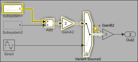
Signal Highlighting in Variant Systems
Tracing a signal that passes through inline variant blocks such as Variant Source and Variant Sink highlights the path of the active variant choice. In this example, the selected signal trace to its source shows the path of the active variant passing through the Variant Source2 block.
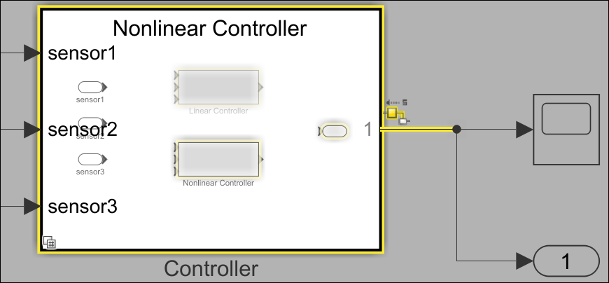
For a Variant Subsystem block, the trace highlights the active choice within the subsystem by default.
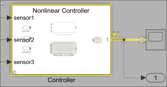
If the Variant activation time parameter of the Variant
Subsystem block is set to code compile, the trace
highlights both the active and inactive choices within the subsystem.
Limitations
The signal tracing tool has the following limitations in its usage:
The signal trace does not preserve bus information when tracing into or out of a referenced model.
Tracing past a Goto block changes the active level to that containing the matching From block. However, this does not guarantee that the matching From block is the active block if there are other valid blocks at the same level.
Signal tracing is unsupported by certain blocks. Unsupported blocks are blocks where:
You cannot trace into them to highlight their contents. Examples of such blocks include but are not limited to Stateflow® charts, Simscape™ subsystems, and function blocks,.
You cannot cross them and continue tracing (e.g. Simscape blocks).
The styling of the signal does not update with modifications to the model when signal tracing is enabled.
The operation to Show All Possible Paths of a Trace does not traverse through referenced models in the same way as it does subsystems. Referenced models are treated as nonvirtual blocks and the impact region will not highlight their contents.
Bus Element Tracing and Highlighting
To trace the source or destination of a bus element using the Signal Hierarchy Viewer:
Select a bus in your model.
In the Simulink Toolstrip, on the Signal tab, select Signal Hierarchy.
The Signal Hierarchy Viewer opens, showing the signal hierarchy for the selected bus.
In the Signal Hierarchy Viewer, select the element name.
In the Signal Hierarchy Viewer, click Source or Destination to highlight source blocks or destination blocks, respectively.
For example, this figure traces a bus element named sine to its source
blocks. The tracing highlights the currently selected bus, a Bus Assignment
block, two Bus Creator blocks, a Sine Wave block, and the
intermediary signals.

The Signal Hierarchy Viewer displays the signal that is currently selected. If you select a different signal line while the Signal Hierarchy Viewer is open, the Signal Hierarchy Viewer updates to the corresponding selection. If you do not select a signal, the Signal Hierarchy Viewer is blank. Thus, tracing the signal via the Signal Hierarchy Viewer requires at least one signal line selected.
For more information, see Signal Hierarchy Viewer.