qammod
Quadrature amplitude modulation (QAM)
Description
Y = qammod(___,Name=Value)InputType=bit sets the type of input signal to
bits.
Examples
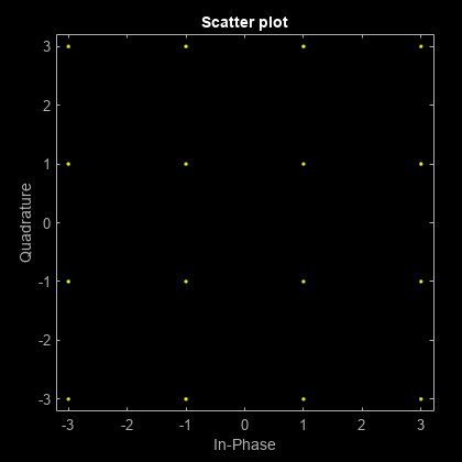
Modulate data using QAM and display the result in a scatter plot.
Set the modulation order to 16 and create a data vector containing each of the possible symbols.
M = 16;
x = (0:M-1)';
Modulate the data using the qammod function.
y = qammod(x,M);
Display the modulated signal constellation using the scatterplot function.
scatterplot(y)
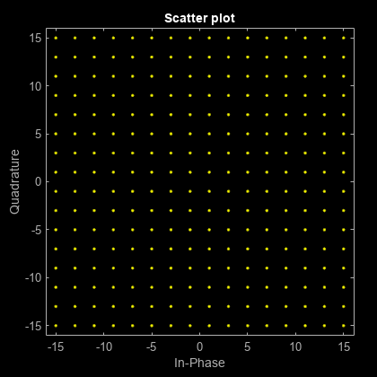
Set the modulation order to 256, and display the scatter plot of the modulated signal.
M = 256;
x = (0:M-1)';
y = qammod(x,M);
scatterplot(y)
Modulate random data symbols using QAM. Normalize the modulator output so that it has an average signal power of 1 W.
Set the modulation order and generate random data.
M = 64;
x = randi([0 M-1],1000,1);
Modulate the data. Use the 'UnitAveragePower' name-value argument to set the output signal to have an average power of 1 W.
y = qammod(x,M,UnitAveragePower=true);
Confirm that the signal has unit average power.
avgPower = mean(abs(y).^2)
avgPower =
1.0070
Plot the resulting constellation.
scatterplot(y)
title('64-QAM, Average Power = 1 W')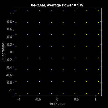
Plot QAM constellations for Gray, binary, and custom symbol mappings.
Set the modulation order, and create a data sequence that includes a complete set of symbols for the modulation scheme.
M = 16;
d = 0:M-1;
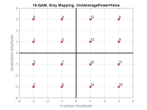
Modulate the data, and plot its constellation. The default symbol mapping uses Gray-coded ordering. The ordering of the points is not sequential.
y = qammod(d,M,PlotConstellation=true);
Repeat the modulation process with binary symbol mapping. The symbol mapping follows a binary-coded order and is sequential.
z = qammod(d,M,'bin',PlotConstellation=true);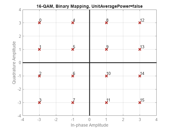
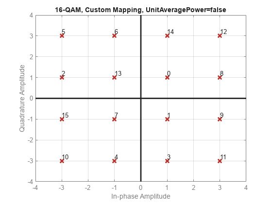
Create a custom symbol mapping.
smap = randperm(M)-1;
Modulate and plot the constellation.
w = qammod(d,M,smap,PlotConstellation=true);
Plot various M-QAM constellations to demonstrate the shape depends on the modulation order.
Define a vector of vlaues for modulation order, , from the number of bits/symbol, .
k = 1:7;  % Number of bits per symbol
M = 2.^k; % Modulation order
Use a for loop to create a data sequence that includes a complete set of symbols for the modulation scheme, modulate the data, and plot the constellation for each modulation order in the range of values in vector k. Note the constellation shape depends on the number of bits per symbol, .
For even values of , the constellation is a square.
For odd values of , the constellation is a cross.
For and , the constellation is a rectangle.
for ii = 1:length(M)
    disp(['k = ',num2str(k(ii))])
    d = 0:M(ii)-1;
    y = qammod(d,M(ii),PlotConstellation=true);

end
k = 1

k = 2

k = 3

k = 4

k = 5

k = 6

k = 7

Modulate a sequence of bits using 64-QAM. Pass the signal through a noisy channel. Display the resultant constellation diagram.
Set the modulation order, and determine the number of bits per symbol.
M = 64;
k = log2(M);
Create a binary data sequence. When using binary inputs, the number of rows in the input must be an integer multiple of the number of bits per symbol.
data = randi([0 1],1000*k,1);
Modulate the signal using bit inputs, and set it to have unit average power.
txSig = qammod(data,M, ...
    InputType='bit', ...
    UnitAveragePower=true);
Pass the signal through a noisy channel.
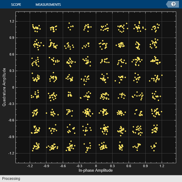
rxSig = awgn(txSig,25);
Plot the constellation diagram.
cd = comm.ConstellationDiagram(ShowReferenceConstellation=false);
cd(rxSig)
Demodulate a fixed-point QAM signal and verify that the data is recovered correctly.
Set the modulation order as 64, and determine the number of bits per symbol.
M = 64;
bitsPerSym = log2(M);
Generate random bits. When operating in bit mode, the length of the input data must be an integer multiple of the number of bits per symbol.
x = randi([0 1],10*bitsPerSym,1);
Modulate the input data using a binary symbol mapping. Set the modulator to output fixed-point data. The numeric data type is signed with a 16-bit word length and a 10-bit fraction length.
y = qammod(x,M,'bin', ...
    InputType='bit', ...
    OutputDataType=numerictype(1,16,10));
Demodulate the 64-QAM signal. Verify that the demodulated data matches the input data.
z = qamdemod(y,M,'bin',OutputType='bit');
s = isequal(x,double(z))
s = logical
   1
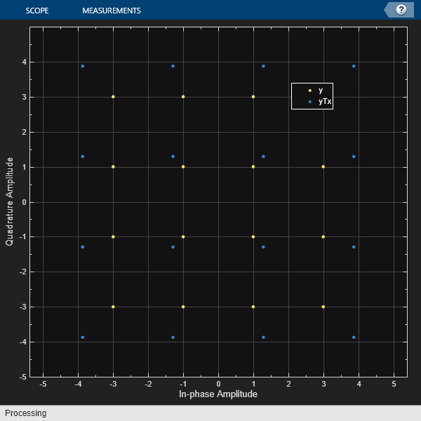
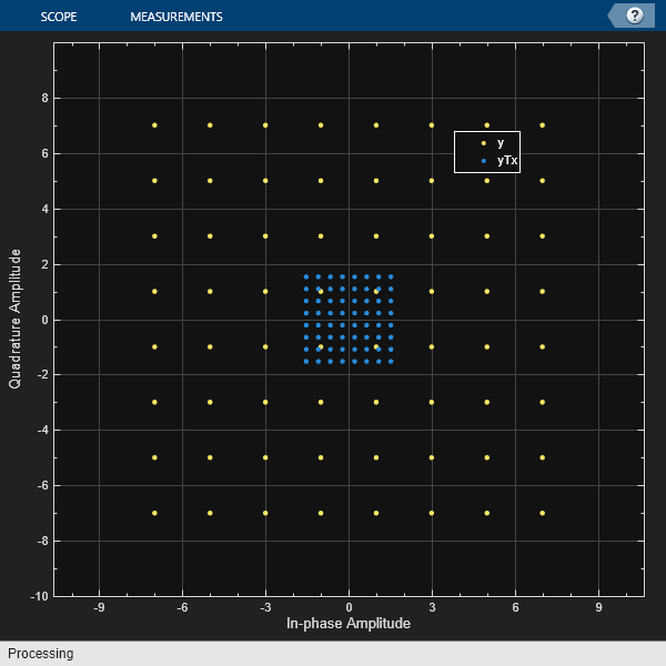
Apply average power normalization for hard decision output when using qammod and qamdemod functions by using the helperAvgPow2MinD utility function. Scale the constellation to the normalized average power, and then plot the reference and scaled constellations.
Compute the minimum distance for symbols based on specified average power and modulation order.
M = 64;
avgPwr = 2;
minD = helperAvgPow2MinD(avgPwr,M);
Modulate a signal composed of random integers in the range [0, M - 1], scale the modulated symbols.
x = randi([0,M-1],1000,1);
y = qammod(x,M);
yTx = (minD/2) .* y;
Verify signal average power approximately equals the specified average power, avgPow.
sigPwr = mean(abs(yTx).^2)
sigPwr =
2.0141
avgPwr
avgPwr =
2
Assign the transmitted signal to the receive signal without applying any RF or channel impairments. With no impairments to distort the received signal, the demodulated matches the original signal. Demodulate symbols using hard decisions, and confirm correct signal demodulation.
yRx = yTx;
z = qamdemod(yRx*2/minD,M);
checkDemodIsEqual = isequal(x,z)
checkDemodIsEqual = logical
   1
refC = qammod([0:M-1]',M);
Show constellation
maxAx = ceil(max(abs(refC)));
cd = comm.ConstellationDiagram(2, ...
    'ShowReferenceConstellation',0, ...
    'ShowLegend',true, ...
    'XLimits',[-(maxAx) maxAx],'YLimits',[-(maxAx) maxAx], ...
    'ChannelNames', ...
    {'y','yTx'});
cd(y,yTx)
Apply peak power normalization for hard decision output when using qammod and qamdemod functions by using the helperPeakPow2MinD utility function. Scale the constellation to the normalized peak power, and then plot the reference and scaled constellations.
Compute the minimum distance for symbols based on specified peak power and modulation order.
M = 16;
pkPwr = 30;
minD = helperPeakPow2MinD(pkPwr,M);
Modulate a signal composed of random integers in the range [0, M - 1], scale the modulated symbols.
x = randi([0,M-1],1000,1);
y = qammod(x,M);
yTx = (minD/2) .* y;
Verify signal peak power approximately equals the specified peak power, pkPow.
sigPwr = max(abs(yTx).^2)
sigPwr =
30
pkPwr
pkPwr =
30
Assign the transmitted signal to the receive signal without applying any RF or channel impairments. With no impairments to distort the received signal, the demodulated matches the original signal. Demodulate symbols using hard decisions, and confirm correct signal demodulation.
yRx = yTx;
z = qamdemod(yRx*2/minD,M);
checkDemodIsEqual = isequal(x,z)
checkDemodIsEqual = logical
   1
refC = qammod([0:M-1]',M);
Show constellation
maxAx = ceil(max(abs(refC)));
cd = comm.ConstellationDiagram(2, ...
    'ShowReferenceConstellation',0, ...
    'ShowLegend',true, ...
    'XLimits',[-(maxAx) maxAx],'YLimits',[-(maxAx) maxAx], ...
    'ChannelNames', ...
    {'y','yTx'});
cd(y,yTx)