Selector
Select input elements from vector, matrix, or multidimensional signal
Libraries:
Simulink /
Signal Routing
HDL Coder /
Signal Routing
Description
The Selector block extracts selected elements of an input vector, matrix, or multidimensional signal based on specified indices. The extracted signals can be grouped differently than the input signals.
Based on the value you enter for the Number of input dimensions parameter, a table of indexing settings is displayed. Each row of the table corresponds to one of the input dimensions in Number of input dimensions. For each dimension, you define the elements of the signal to work with. Specify a vector signal as a 1-D signal and a matrix signal as a 2-D signal. When you configure the Selector block for multidimensional signal operations, the block icon changes.
For example, assume a 6-D signal with a one-based index mode. The table of the
Selector block dialog box changes to include one row for each
dimension. If you define dimensions as shown in the next table, the output is Y
= U(1:end,2:6,[1 3 5],Idx4:Idx4+7,Idx5,Idx6(1):Idx6(2)), where
Idx4, Idx5, and Idx6 are
the index ports for dimensions 4, 5, and 6. For more information, see Select Elements from Multidimensional Array Using Selector Block.
| Row | Index Option | Index | Output Size |
|---|---|---|---|
| 1 | Select all | ||
| 2 | Starting index (dialog) | 2 | 5 |
| 3 | Index vector (dialog) | [1 3 5] | |
| 4 | Starting index (port) | 8 | |
| 5 | Index vector (port) | ||
| 6 | Starting and ending indices (port) |
You can use an array of buses as an input signal to a Selector block. For details about defining and using an array of buses, see Group Nonvirtual Buses in Arrays of Buses.
Note
Selector block does not change the dimensionality (number of dimensions) of the input signals. If you need to change the dimensionality of the signal to the dimensions you specify, use Reshape block.
Examples
This example shows two Selector blocks with the same kind of input signals, but two different Index Option settings.

Both Selector blocks select 7 values from the input signal that feeds the input port. The Selector1 block outputs a fixed-size signal, whereas the Selector2 block outputs a variable-size signal whose compiled signal dimension is 10 instead of 7.
The Selector1 block sets Index Option to Index vector (port), which uses the input signal from Constant1 as the index vector. The dimension of the input signal is 7, so the Display block shows the 7 values of the Constant1 block. The Selector2 block sets the Input port size parameter to 10, which is the size of the largest input signal to the Selector2 block.
The Selector2 block also sets the Index Option to Starting and ending indices (port). The output is then set to the size of Input port size parameter (10), even though the size of the input signal is 7.
This example shows how to select elements from a multidimensional array using a Selector block. In this example, you use different indexing options of the block to select and extract the elements of a 6-D array.
Open the model.
mdl = "extractmultidimarray.slx";
open_system(mdl)
Configure the Block
The input array U is a 6-D array with dimensions 6-by-6-by-6-by-9-by-7-by-5 with a one-based index mode. The model loads the input array from the inputSignal file by using model PreLoadFcn callback. You can select elements from each dimension of the array using the following selection semantics and different index options. In this example, one-based index mode is used for the input array. Consequently, the row numbers (first column of the table) directly indicate the dimensions of the input array. For example, row 1 indicates dimension 1 of the input array, and so on.
To extract all of the elements of dimension 1, use
Select All.To extract the third and fourth elements of dimension 2, use
Starting Index (dialog). Set Index column to3and Output Size column to2.To extract the first, third, and fifth element of dimension 3, use
Index vector (dialog). Set Index column to [1 3 5].To extract the first eight elements of dimension 4, use
Starting Index (port). The Constant blockConst1connected to port provides the starting index value1. Set the Output Size column to8.To extract the second, third, and fourth elements of dimension 5, use
Index vector (port). The Constant blockConst2connected to port provides the index value [2:4].To extract a range of elements from dimension 6, use
Starting and ending
                                    indices (port)
. The selection ranges from the third to the fifth element. The Constant blockConst3connected to port provides the range [3 5].

Log signal
Run the simulation and use the To Workspace block to log the signal to the variable Y.
Y = sim(mdl);
Extended Examples
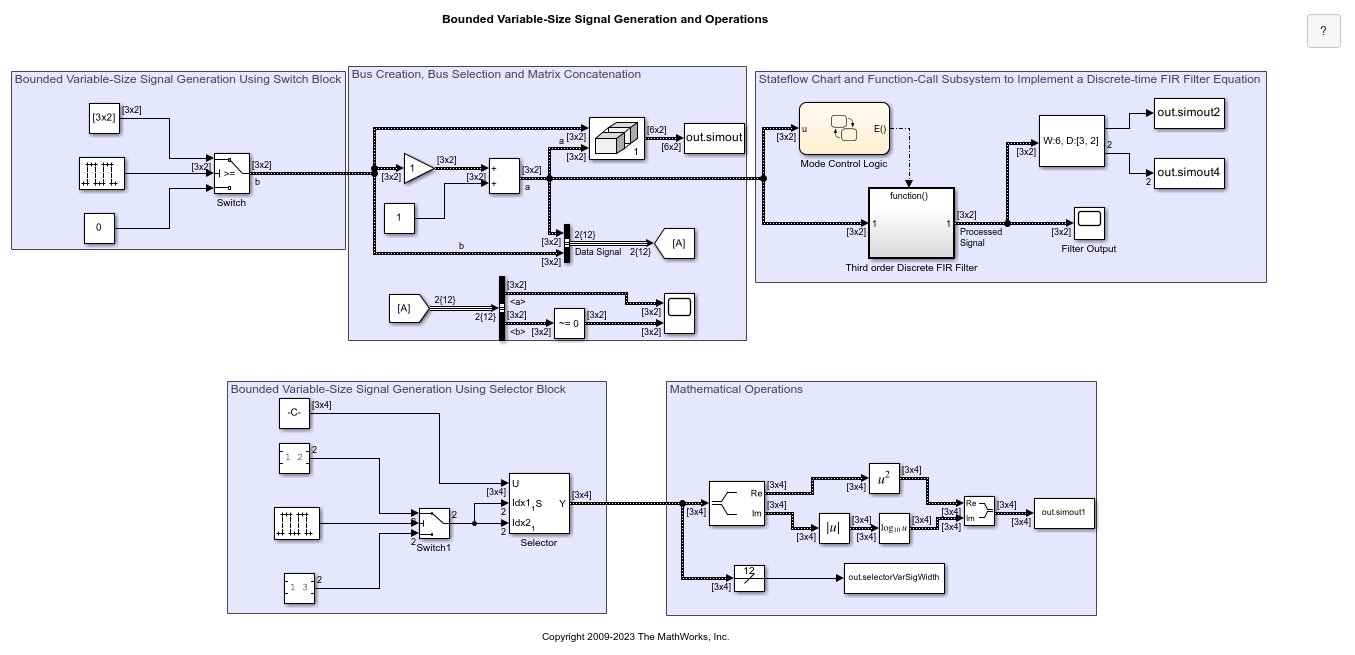
Bounded Variable-Size Signal Basic Operations
Generate bounded variable-size signals and illustrates some of the operations using those signals. In this example, you generate variable-size signals using the Selector block and the Switch block. The signals are used in math operations, bus creation, bus selection, matrix concatenation and to implement a discrete filter equation.

Multimode Variable-Size Signal
Use different operation modes to correspond to different signal sizes.

Model Arrays of Buses
Use arrays of buses to represent structured data compactly.
Limitations
The Index parameter is not tunable during simulation. If the Index Option for a dimension is set to
Index vector (dialog)orStarting index (dialog)and you specify a symbolic value, including aSimulink.Parameterobject, for the corresponding Index in the block dialog box, then the instantaneous value at the start of simulation will be used throughout the simulation, and the parameter will appear as an inlined value in the generated code. See Tune and Experiment with Block Parameter Values. You can adjust the selection index dynamically by using index ports.
Ports
Input
Output
Parameters
Block Characteristics
Data Types |
|
Direct Feedthrough |
|
Multidimensional Signals |
|
Variable-Size Signals |
|
Zero-Crossing Detection |
|