Accelerating NASA GN&C Flight Software Development
By Scott Tamblyn, NASA, Joel Henry, NASA, and John Rapp, Lockheed Martin
When the guidance, navigation, and control (GN&C) system for the Orion crew vehicle undergoes Critical Design Review (CDR), more than 90% of the flight software will already be developed—a first for NASA on a project of this scope and complexity. This achievement is due in large part to a new development approach using Model-Based Design.
Most NASA GN&C projects follow a traditional process: Domain experts and analysts specify the behavior of the core algorithms in detailed requirements documents. Following CDR, these documents are handed off to the flight software engineers for implementation into the formal flight software. Producing the specification document alone often requires years of effort, and because coding can begin only after the spec is complete, it can be years before there is any code to test.
The design and development of the GN&C flight algorithms for Orion is a partnership between NASA, Lockheed Martin, and other contractors. Model-Based Design has helped these organizations work on both the GN&C algorithm and flight software development concurrently. Simulink® models serve as an executable specification from which flight software is automatically generated. As a result, the domain experts—the GN&C analysts—work directly with the executable algorithm models rather than with documents that must then be interpreted by software developers (Figure 1).
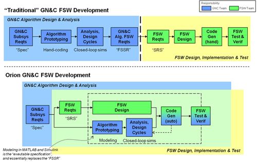
Merging the design and analysis environment with the flight software development environment enables the joint team to identify and resolve problems earlier and has the potential to reduce overall development time by a year or more.
Laying the Groundwork for the New Approach
While Lockheed Martin was already familiar with Model-Based Design, this approach represented a paradigm shift for many NASA engineers and contractors. To prepare the ground, lead GN&C and flight software engineers collaborated in detailing the benefits of the new development process, and explained how it would change the roles and responsibilities of the GN&C analysts and flight software engineers.
Modeling standards were developed to enable the approximately 100 engineers from multiple organizations working on the GN&C algorithms to develop consistent models, understand each other's work, and collaborate efficiently. These standards ensure that all models are clear and readable—particularly important for a large team using the models as documentation. The standards were based on lessons learned in earlier projects and on MathWorks Automotive Advisory Board (MAAB) guidelines.
Developing and Integrating GN&C Algorithms
The first step in developing the GN&C system architecture was the creation of the 'Empty-Box Architecture' (EBA). The EBA contains approximately 100 functional modules, or computer software units (CSUs).
The engineer or subteam responsible for a CSU assembles a model comprising one hundred or more Simulink library blocks and components. Because the CSUs are specified as Model Reference blocks, each unit can be thoroughly simulated on the desktop before it is handed off to the flight software team. The engineer then uses Simulink Check™ and the Simulink Model Advisor tool to verify that the model meets the modeling standards. The engineer also generates code to ensure that there are no problems in the model that would preclude code generation. When delivering the CSU, the engineer provides both the Simulink model and the test inputs and expected test outputs from the unit tests.
To validate the overall GN&C software, as well, the team runs the higher-level model composed of all functional units in closedloop simulations to further debug and test the algorithms. In these situations, NASA relies on Trick, a high-fidelity, six-degree-of-freedom simulation infrastructure that NASA has been refining for more than 20 years. The simulation environment includes mathematical models of the vehicle's sensors (such as inertial measurement units and star trackers) and effectors (such as reaction control systems), as well as aerodynamics, gravity, and the space environment.
The higher-level model is linked to the Trick environment via a socket connection. This setup enables engineers to debug their CSU algorithms in the full-featured Simulink environment while running closed-loop simulations. For example, engineers can simulate the atmospheric entry phase of flight and use scopes in Simulink to observe signals in their own CSU or anywhere in the EBA.
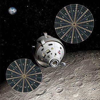
Orion
Designed for deep space missions, NASA's Orion crew exploration vehicle will carry a new generation of astronauts far beyond low Earth orbit to multiple destinations throughout our solar system, such as asteroids, the moon, and eventually, Mars. Orion will replace the space shuttle as the agency's principal vehicle for human space exploration.
Generating Code with Embedded Coder
Because the C++ flight code is automatically generated from the Simulink models, most flight software coding will be completed before CDR. In addition to saving time and reducing risk, code generation with Embedded Coder® provides three advantages at this stage of the program: First, it enables us to verify that the code that will ultimately get deployed aboard the target vehicle can be generated and that it produces the same results as the Simulink simulations of the source models. Second, code generation enables engineers who are accustomed to writing their own code to inspect the generated C++ code and even debug directly in the code. Third, it enables analysts to dramatically realize closed-loop run-time performance by embedding the generated code directly into the Trick simulation infrastructure.
Simulink is ideal for running closed-loop simulations because its interactive, visual environment helps engineers identify and resolve defects quickly. For full analytical verification testing, however, simulation speed is a more important consideration because of the need to run hundreds of thousands of Monte Carlo simulations for a range of scenarios.
Closed-loop simulations employing the generated code embedded in Trick perform approximately 10 times faster than real time. As a result, a full 10-day Orion mission can be simulated in just one day. Engineers have already conducted entry-stage simulations using both approaches— using the Simulink model to drive Trick, and embedding the generated code into Trick. When compared, the results of the two simulations were found to be bit-for-bit true; they matched down to the lowest level.
Blazing a Trail
This GN&C project is blazing a new trail for NASA in many ways. Simulink and Embedded Coder are enabling a large team of domain experts from NASA, Lockheed, and other contractors to develop algorithms for complicated trajectories and scenarios, run simulations within a legacy simulation environment, and generate flight software code that will ultimately be deployed on the vehicle.
On long-term projects like this one, it is not uncommon for agency requirements and priorities to shift. With the algorithms captured in models rather than in low-level code, the engineers are well positioned to take the project in whatever direction it needs to go.
Published 2011 - 91876v00