getPathFilters
Get path filter impulse response for link-level MIMO channel
Description
pathFilters = getPathFilters(channel)channel. Specify the channel as an nrCDLChannel, nrTDLChannel, or nrHSTChannel
System object™. Use pathFilters together with the
pathGains output argument returned by the channel object to reconstruct
a perfect channel estimate.
Note
When
channelis annrHSTChannelSystem object with HST-SFN channel profile, the path filters are time-varying and depend on the state of the channel. In this case, the returned path filters always relate to the last call of the channel object. For all other channels, the path filters do not change with the channel object call.
Examples
Reconstruct the channel impulse response and perform timing offset estimation using path filters of a Clustered Delay Line (CDL) channel model with delay profile CDL-D from TR 38.901 Section 7.7.1.
Define the channel configuration structure using an nrCDLChannel System object. Use delay profile CDL-D, a delay spread of 10 ns, and UE velocity of 15 km/h:
v = 15.0;                    % UE velocity in km/h
fc = 4e9;                    % carrier frequency in Hz
c = physconst('lightspeed'); % speed of light in m/s
fd = (v*1000/3600)/c*fc;     % UE max Doppler frequency in Hz

cdl = nrCDLChannel;
cdl.DelayProfile = 'CDL-D';
cdl.DelaySpread = 10e-9;
cdl.CarrierFrequency = fc;
cdl.MaximumDopplerShift = fd;
Configure the transmit array as [M N P Mg Ng] = [2 2 2 1 1], representing 1 panel (Mg=1, Ng=1) with a 2-by-2 antenna array (M=2, N=2) and P=2 polarization angles. Configure the receive antenna array as [M N P Mg Ng] = [1 1 2 1 1], representing a single pair of cross-polarized co-located antennas.
cdl.TransmitAntennaArray.Size = [2 2 2 1 1];
cdl.ReceiveAntennaArray.Size = [1 1 2 1 1];
Create a random waveform of 1 subframe duration with 8 antennas.
SR = 15.36e6;
T = SR * 1e-3;
cdl.SampleRate = SR;
cdlinfo = info(cdl);
Nt = cdlinfo.NumTransmitAntennas;

txWaveform = complex(randn(T,Nt),randn(T,Nt));
Transmit the input waveform through the channel.
[rxWaveform,pathGains] = cdl(txWaveform);
Obtain the path filters used in channel filtering.
pathFilters = getPathFilters(cdl);
Perform timing offset estimation using nrPerfectTimingEstimate.
[offset,mag] = nrPerfectTimingEstimate(pathGains,pathFilters);
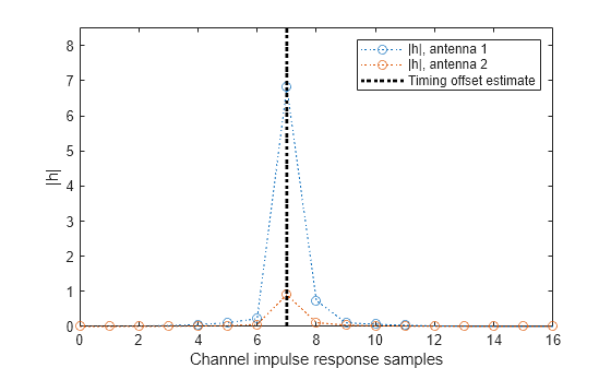
Plot the magnitude of the channel impulse response.
[Nh,Nr] = size(mag);
plot(0:(Nh-1),mag,'o:');
hold on;
plot([offset offset],[0 max(mag(:))*1.25],'k:','LineWidth',2);
axis([0 Nh-1 0 max(mag(:))*1.25]);
legends = "|h|, antenna " + num2cell(1:Nr);
legend([legends "Timing offset estimate"]);
ylabel('|h|');
xlabel('Channel impulse response samples');
Create an HST-SFN multi-tap channel model with one receive antenna.
hst = nrHSTChannel( ...
    ChannelProfile='HST-SFN', ...
    NumReceiveAntennas=1);
Set the distance between the gNodeBs to 700 m. Set the minimum distance between the railway track and the gNodeBs to 150 m.
hst.Ds = 700;
hst.Dmin = 150;
Set the train velocity to 500 km/h. Set the maximum Doppler shift to 870 Hz.
hst.Velocity = 500;
hst.MaximumDopplerShift = 870;
Disable channel filtering.
hst.ChannelFiltering = false;
Set the sample rate and the number of channel samples to calculate 1 ms of path gains samples.
hst.SampleRate = 30.72e6;
hst.NumTimeSamples = hst.SampleRate*1e-3;
Set the initial time of the channel to configure the starting position of the train. The train position relative to a remote gNodeB determines the delay of each gNodeB signal.
hst.InitialTime = (hst.Ds/3)/(hst.Velocity/3.6);
Retrieve the path gains from the channel.
pathGains = hst();
Obtain the channel path filter responses relative to the previous channel call. The delay of each gNodeB signal changes over time.
pathFilters = getPathFilters(hst);
Estimate the channel delay by obtaining the timing offset.
offset = nrPerfectTimingEstimate(pathGains,pathFilters);
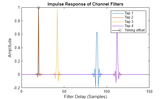
Display the path filters and the estimated channel delay.
plot(0:size(pathFilters,1)-1,pathFilters);
hold on
stem(repmat(offset,1,hst.NumTaps),pathFilters(1+offset,:),'k')
legend(["Tap "+ (1:hst.NumTaps) "Timing offset"])
xlabel('Filter Delay (Samples)')
ylabel('Amplitude')
title('Impulse Response of Channel Filters')
Input Arguments
Output Arguments
References
[1] 3GPP TR 38.901. “Study on channel model for frequencies from 0.5 to 100 GHz.” 3rd Generation Partnership Project; Technical Specification Group Radio Access Network.
[2] 3GPP TS 38.101-4. “NR; User Equipment (UE) radio transmission and reception; Part 4: Performance requirements.” 3rd Generation Partnership Project; Technical Specification Group Radio Access Network.