installedAntenna
Installed antenna setup
Description
The installedAntenna object creates an installed antenna
setup that enables you to mount antennas on a platform for analysis.
Installed antenna analysis involves an electrically large structure called a platform. Around this platform, different antenna elements are placed. You can analyze the effects of the platform on the antenna performance. Installed antenna analysis is commonly used in aerospace, defense, and automotive applications. The best examples of a platform in these applications are an aircraft, a ship, and an automobile respectively.
Another common application of installed antenna analysis is to determine the interference of different antennas placed on a large platform.
Note
installedAntenna only models pure metal structures.
Creation
Description
ant = installedAntenna
ant = installedAntenna(PropertyName=Value)PropertyName is the property name and
Value is the corresponding value. You can specify
several name-value arguments in any order as
PropertyName1=Value1,...,PropertyNameN=ValueN.
Properties that you do not specify, retain their default values.
For example, p = platform(FileName='plate.stl'); ant =
installedAntenna(Platform=p) uses the geometry in the
'plate.stl' file to create a platform for antenna
installation and analysis.
Output Arguments
Properties
Object Functions
axialRatio | Calculate and plot axial ratio of antenna or array |
beamwidth | Beamwidth of antenna |
charge | Charge distribution on antenna or array surface |
current | Current distribution on antenna or array surface |
correlation | Correlation coefficient between two antennas in array |
efficiency | Calculate and plot radiation efficiency of antenna or array |
EHfields | Electric and magnetic fields of antennas or embedded electric and magnetic fields of antenna element in arrays |
feedCurrent | Calculate current at feed for antenna or array |
impedance | Calculate and plot input impedance of antenna or scan impedance of array |
info | Display information about antenna, array, or platform |
mesh | Generate and view mesh for antennas, arrays, and custom shapes |
meshconfig | Change meshing mode of antenna, array, custom antenna, custom array, or custom geometry |
msiwrite | Write antenna or array analysis data to MSI planet file |
pattern | Plot radiation pattern of antenna, array, or embedded element of array |
patternAzimuth | Azimuth plane radiation pattern of antenna or array |
patternElevation | Elevation plane radiation pattern of antenna or array |
patternSystem | Visualize radiation patterns of multiple antennas installed on platform |
peakRadiation | Calculate and mark maximum radiation points of antenna or array on radiation pattern |
rcs | Calculate and plot monostatic and bistatic radar cross section (RCS) of platform, antenna, or array |
returnLoss | Calculate and plot return loss of antenna or scan return loss of array |
show | Display antenna, array, AI-based antenna, platform, or shape |
solver | Specify FMM and FEM solver settings during electromagnetic analysis |
sparameters | Calculate S-parameters for antenna or array |
stlwrite | Write mesh information to STL file |
vswr | Calculate and plot voltage standing wave ratio (VSWR) of antenna or array element |
Examples
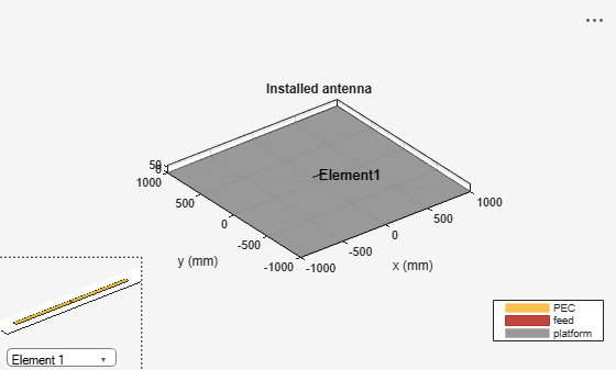
Create a default installed antenna.
ant = installedAntenna
ant =
  installedAntenna with properties:

           Platform: [1×1 platform]
            Element: [1×1 dipole]
    ElementPosition: [0 0 0.0750]
          Reference: 'feed'
        FeedVoltage: 1
          FeedPhase: 0
               Tilt: 0
           TiltAxis: [1 0 0]
         SolverType: 'MoM-PO'
show(ant);
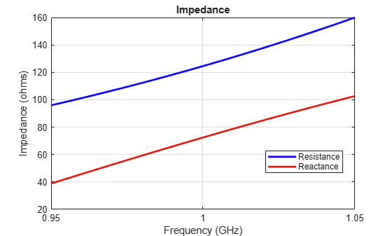
Calculate the impedance of the antenna.
figure;
impedance(ant, linspace(950e6, 1050e6, 51));
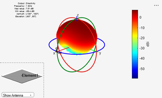
Visualize the pattern of the antenna.
figure;
pattern(ant, 1e9);
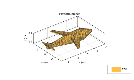
Create a platform from the STL file containing the geometry information of a glider. View the platform.
plat = platform(FileName="glider.stl", Units="m");
figure
show(plat);
Design a regular and a circular microstrip patch antenna operating at 2GHz. Install these antennas on the glider wings. View the glider with installed antennas.
elem1 = design(patchMicrostrip, 2e9);
elem2 = design(patchMicrostripCircular, 2e9);
ant = installedAntenna(Platform=plat, Element={elem1, elem2},...
    ElementPosition=[-3.15 1.1 0.12; -3.15 -1.1 0.12]);
figure
show(ant)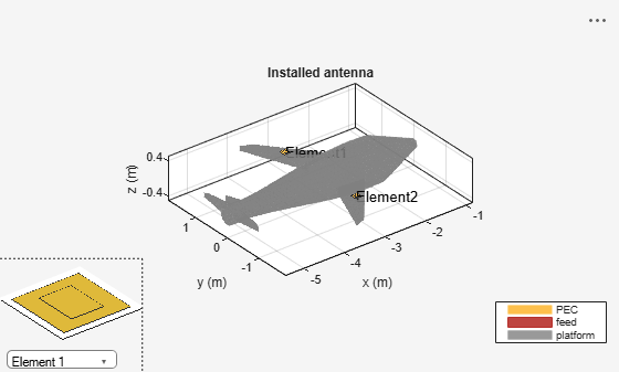
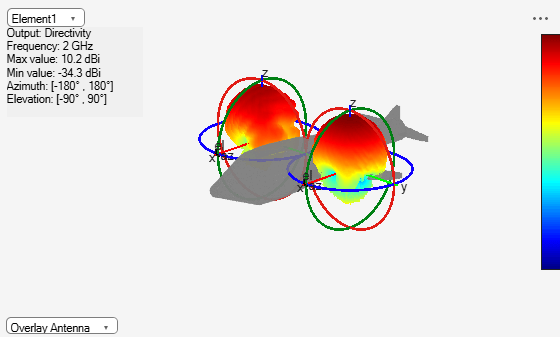
Visualize the radiation patterns of the installed patch antennas.
figure
patternSystem(ant, 2e9, ElementNumber=1:2)
Algorithms
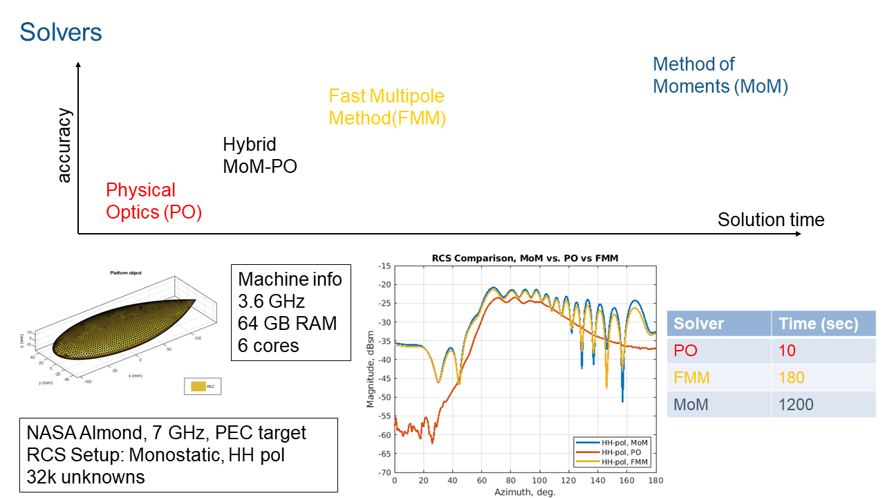
The default solver for installed antenna analysis is the hybrid MoM-PO ( Method of moments and physical optics) solver. This is a hybrid solver, with less stringent requirements on the mesh. This approach does not have full-wave accuracy since the electrically large portion of the geometry is handled using the physical optics approach. For more information on this solver see, Hybrid MoM-PO Method for Metal Antennas with Large Scatterers.
For full wave accuracy in installed antenna analysis you can use the FMM (fast multiple method) solver. This solver does not fill and store a matrix of interactions and enables the solution of large structures which is not possible when using the MoM solver. For open geometries, this solver builds a preconditioner matrix internally. The preconditioner matrix is sparse but might be less sparse for larger structures. Preconditioner matrices are not built for closed geometries. When using the FMM, you have an option to use the solver object to set up the number of iterations and the relative error. In some circumstances it might be useful to study the nature of the problem and its convergence characteristics by reducing the number of iterations or the relative error initially or both. The FMM solver does need approximately 10 elements per wavelength in the mesh. The number of elements does impact the convergence of the solution. For more information on FMM solvers, see Fast Multipole Method for Large Structures.
For wavelength and sub-wavelength scale structures, with or without dielectric you can use an MoM (method of moments)solver. For more information on MoM solver, see Method of Moments Solver for Metal Structures and Method of Moments Solver for Metal and Dielectric Structures.
Version History
Introduced in R2019a