Carrier Synchronizer
Compensate for carrier frequency offset
Libraries:
Communications Toolbox /
Synchronization
Description
The Carrier Synchronizer block compensates for carrier frequency and phase offsets in signals that use single-carrier modulation schemes. The carrier synchronizer algorithm is compatible with BPSK, QPSK, OQPSK, 8-PSK, PAM, and rectangular QAM modulation schemes.
Note
Modulation-type dependent phase ambiguities may be introduced by the synchronization algorithm. For more information, see Potential Phase Ambiguity.
This icon shows the block without optional port.![]()
Examples
Correct for a phase and frequency offset imposed on a noisy 16-QAM channel by using the Carrier Synchronizer block.
The doc_qamcarriersync model configures a 16-QAM signal, adds phase and frequency offset, passes the signal through a noisy AWGN channel, and then corrects the offsets by using the Carrier Synchronizer block.
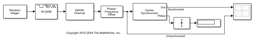
The constellation diagram shows the signal constellation before and after carrier synchronization. Before synchronization, the signal appears as a spiral pattern that results from a phase and frequency offset. After the carrier synchronizer converges to a solution, the signal symbols are grouped around the reference constellation.

Experiment with the parameters in the Phase/Frequency Offset and Carrier Synchronizer blocks. By varying these parameters, you can change how quickly the output conforms to an ideal 16-QAM constellation. If the signal does not converge to the expected constellation, additional measures can be taken to achieve successful recovery.
While correcting for a phase and frequency offset imposed on a QPSK signal, the Carrier Synchronizer block introduces symbol phase ambiguity that increases the symbol error rate (SER). To resolve the symbol phase ambiguity, this example adds a frame preamble to the transmitted signal and includes a subsystem block that computes the phase ambiguity introduced by the carrier synchronization.
The doc_carrsync_resolve_ambig model configures a QPSK-modulated data frame that includes a Barker sequence preamble and random data. The data frame gets impaired by phase and frequency offsets and an AWGN channel. A Phase/Frequency Offset block sets the phase offset to 45 degrees and frequency offset to 1 kHz. The frequency offset is 1% of the 10 kHz sample rate. A Carrier Synchronizer block corrects the offsets but introduces symbol phase ambiguity that results in a poor symbol error rate (SER).
The model initializes variables used to configure block parameters by using the InitFcn callback function. For more information, see Model Callbacks (Simulink).

The constellation diagram shows the transmitted signal along with the signal constellation before and after carrier synchronization. Before synchronization, the phase and frequency offset cause the constellation points to shift around outlining a circle. After the carrier synchronizer converges to a solution, the signal symbols are grouped around the reference constellation but there may be a symbol phase ambiguity in the placement of constellation points that results in symbol errors. The model computes the SER before and after resolution of symbol phase ambiguity. Removing the phase ambiguity reduces the SER dramatically.

Ports
Input
Output
Parameters
Block Characteristics
Data Types |
|
Multidimensional Signals |
|
Variable-Size Signals |
|
More About
Algorithms
The algorithm implements a closed-loop compensator that uses the PLL-based algorithm described in [1]. The output of the synchronizer, yn, is a frequency-shifted version of the complex input signal, xn, for the nth sample. The synchronizer output is where λn is the output of the direct digital synthesizer (DDS). The DDS is the discrete-time version of a voltage-controlled oscillator and is a core component of discrete-time phase locked loops. The DDS works as an integration filter.
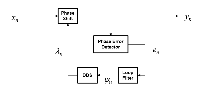
To correct for the frequency offset, first the algorithm determines the phase error, en. The value of the phase error depends on the modulation scheme.
| Modulation | Phase Error |
|---|---|
| QAM or QPSK | For a detailed description of this equation, see [1]. |
| BPSK or PAM | For a detailed description of this equation, see [1]. |
| 8-PSK | For a detailed description of this equation, see [2]. |
| OQPSK |
|
To ensure system stability, the phase error passes through a biquadratic loop filter governed by
where ψn is the output of the loop filter at sample n, and gI is the integrator gain. The integrator gain is determined from the equation
where
Bn is the normalized loop bandwidth
ζ is the damping factor
K0 is the phase recovery gain and equals the number of samples per symbol.
Kp is the phase error detector gain and is determined by the modulation type.
| Modulation | Kp |
|---|---|
| BPSK, PAM, QAM, QPSK, or OQPSK | 2 |
| 8-PSK | 1 |
The output of the loop filter is then passed to the DDS. The DDS is another biquadratic loop filter whose expression is based on the forward Euler integration rule
where gP is the proportional gain that is expressed as
The info object function returns estimates of the
normalized pull-in range, the maximum frequency lock delay, and the maximum phase lock
delay. The normalized pull-in range, (Δf)pull-in, is expressed in radians and estimated as
The expression for (Δf )pull-in becomes less accurate as approaches 1.
The maximum frequency lock delay, TFL, and phase lock delay, TPL, are expressed in samples and estimated as
References
[1] Rice, Michael. Digital Communications: A Discrete-Time Approach. Upper Saddle River, NJ: Prentice Hall, 2008. pp. 359–393.
[2] Huang Zhijie, Yi Zhiqiang, Zhang Ming and Wang Kuang, "8PSK demodulation for new generation DVB-S2," 2004 International Conference on Communications, Circuits and Systems (IEEE Cat. No.04EX914), Chengdu, 2004, pp. 1447-1450 Vol.2, doi: 10.1109/ICCCAS.2004.1346447.
Extended Capabilities
Version History
Introduced in R2015a
See Also
Blocks
- Symbol Synchronizer | Coarse Frequency Compensator | Phase/Frequency Offset | Second-Order Section Filter