Indoor MIMO-OFDM Communication Link Using Ray Tracing
This example shows how to perform ray tracing in an indoor environment and use the results to build a channel model for a link level simulation with the MIMO-OFDM technique.
Introduction
Ray tracing [1] has become a popular technique for radio frequency (RF) analysis, site planning, channel modelling, and link level analysis due to the trend for modern communications systems to operate at RF frequencies in the tens of GHz range. Unlike stochastic models, the ray tracing method is 3-D environment and transceiver sites specific and can have high sensitivity in the surrounding environment. Without a simple formula to calculate distance-based path losses, the ray tracing method relies on numeric simulations, and is typically less costly than field measurements. Results from ray tracing can be used to build multipath channel models for communication systems. For example, a ray tracing based channel model has been specified in Section 8 of TR 38.901 [2] for 5G and in IEEE 802.11ay for WLAN [3].
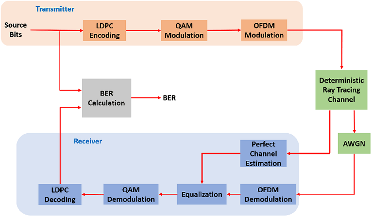
This example starts with ray tracing analysis between one transmitter site and one receiver site in a 3-D conference room. Computed rays are used to construct a deterministic channel model which is specific for the two sites. The channel model is used in the simulation of a MIMO-OFDM communication link. This diagram characterizes the communication link.
The ray tracing is performed in an indoor environment. The same ray tracing methods can be applied to build channel models for indoor or outdoor environments. For ray tracing analysis in an outdoor urban setting, refer to the Urban Link and Coverage Analysis Using Ray Tracing example.
3-D Indoor Scenario
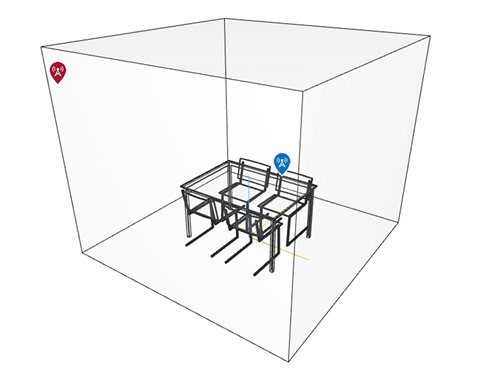
Specify the indoor 3-D map in STL format for a small conference room with one table and four chairs. The STL format is one of the most common 3-D map formats and can often be converted from other 3-D map formats in a variety of 3-D software.
mapFileName = "conferenceroom.stl";Define carrier frequency at 5.8 GHz and calculate wavelength
fc = 5.8e9;
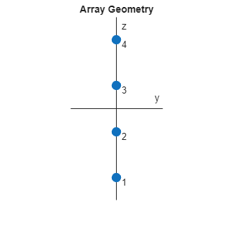
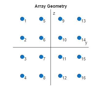
lambda = physconst("lightspeed")/fc;The transmit antenna is a 4-element uniform linear array (ULA) which has twice of the wavelength between the elements. The receive antenna is a 4x4 uniform rectangular array (URA) which has one wavelength between the elements. Both antennas are specified by an arrayConfig object.
txArray = arrayConfig(Size=[4 1],ElementSpacing=2*lambda);
rxArray = arrayConfig(Size=[4 4],ElementSpacing=lambda);
Use the helperViewArray function to visualize the ULA and URA geometries where antenna elements are numbered for input/output streams.
helperViewArray(txArray);
helperViewArray(rxArray);
Specify a transmitter site close to the upper corner of the room, which can be a Wi-Fi access point. Specify a receiver site slightly above the table and in front of a chair to represent a laptop or mobile device.
tx = txsite("cartesian", ...
    Antenna=txArray, ...
    AntennaPosition=[-1.46; -1.42; 2.1], ...
    TransmitterFrequency=fc);

rx = rxsite("cartesian", ...
    Antenna=rxArray, ...
    AntennaPosition=[.3; .3; .85], ...
    AntennaAngle=[0;90]);
Use the siteviewer function with the map file specified to view the scene in 3-D in Site Viewer. Use the show function to visualize the transmitters and receivers.
siteviewer(SceneModel=mapFileName);
show(tx,ShowAntennaHeight=false)
show(rx,ShowAntennaHeight=false)
Pan by left-clicking, zoom by right-clicking or by using the scroll wheel, and rotate the visualization by clicking the middle button and dragging or by pressing Ctrl and left-clicking and dragging.
Ray Tracing
Perform ray tracing analysis between the transmitter and receiver sites and return the comm.Ray objects, using the shooting and bouncing rays (SBR) method. Specify the surface material of the scene as wood and search for rays with up to 2 reflections. The SBR method supports up to 10 order of reflections.
pm = propagationModel("raytracing", ...
    CoordinateSystem="cartesian", ...
    Method="sbr", ...
    AngularSeparation="low", ...
    MaxNumReflections=2, ...
    SurfaceMaterial="wood");

rays = raytrace(tx,rx,pm);
Extract the computed rays from the cell array return.
rays = rays{1,1};Examine the ray tracing results by looking at the number of reflections, propagation distance and path loss value of each ray. There are 24 rays found (one line-of-sight ray, 6 rays with one reflection, and 17 rays with two reflections).
[rays.NumInteractions]
ans = 1×24

    0    1    1    1    1    1    1    2    2    2    2    2    2    2    2    2    2    2    2    2    2    2    2    2
[rays.PropagationDistance]
ans = 1×24

    2.7602    2.8118    2.8487    2.8626    3.2029    4.6513    4.6719    2.8988    2.9125    2.9481    3.2475    3.2916    3.3243    4.6821    4.7247    4.7331    4.7433    4.7936    4.9269    4.9464    5.9869    6.7170    8.0161    8.0460
[rays.PathLoss]
ans = 1×24

    56.5350    68.2594    70.1109    68.4824    73.3105    75.0911    75.1708    83.0074    83.4028    82.9619    84.6714    84.9932    85.7742    85.0379    83.0395    85.2208    89.4165    89.5028    85.6436    85.6669    90.3408    94.8430    95.6098    95.6684
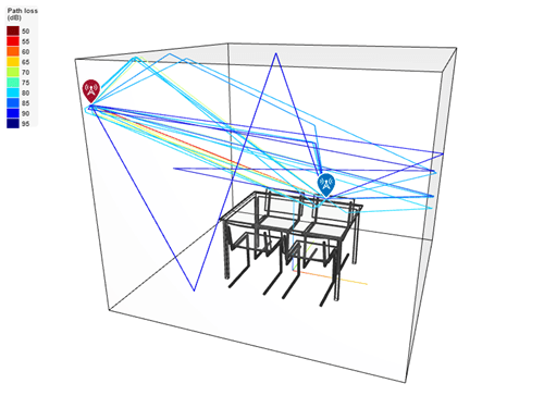
Use the plot function to plot the rays in the 3-D scene in Site Viewer. Each ray is colored based on its path loss value. Click on a ray to view information about that ray.
plot(rays,Colormap=jet,ColorLimits=[50, 95])
Deterministic Channel Model from Ray Tracing
Create a deterministic multipath channel model using the above ray tracing results. Specify the instantaneous velocity of the receiver to reflect typical low mobility of a device in an indoor environment.
rtChan = comm.RayTracingChannel(rays,tx,rx);
rtChan.SampleRate = 300e6;
rtChan.ReceiverVirtualVelocity = [0.1; 0.1; 0]
rtChan =
  comm.RayTracingChannel with properties:

                      SampleRate: 300000000
                 PropagationRays: [1×24 comm.Ray]
        MinimizePropagationDelay: true
                   TransmitArray: [1×1 arrayConfig]
    TransmitArrayOrientationAxes: [3×3 double]
                    ReceiveArray: [1×1 arrayConfig]
     ReceiveArrayOrientationAxes: [3×3 double]
         ReceiverVirtualVelocity: [3×1 double]
       NormalizeImpulseResponses: true
         NormalizeChannelOutputs: true
                ChannelFiltering: true
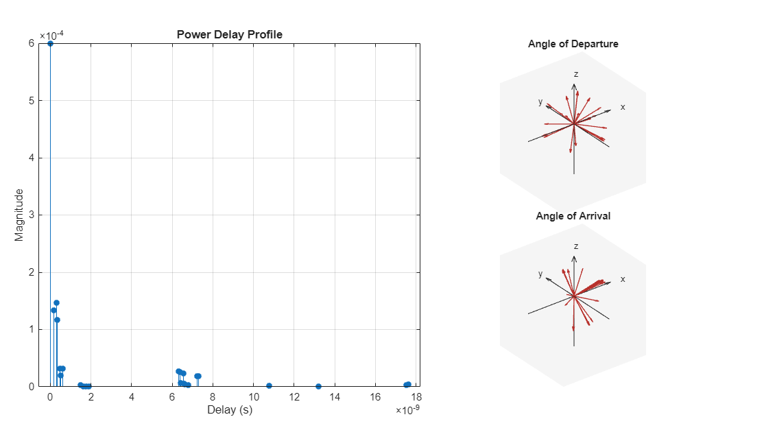
Use the showProfile object function to visualize the power delay profile (PDP), angle of departure (AoD) and angle of arrival (AoA) of the rays in the channel. In the visualization, the PDP has taken into account the transmit and receive array pattern gains in addition to the path loss for each ray.
showProfile(rtChan);
Use the info object function to obtain the number of transmit and receive elements.
rtChanInfo = info(rtChan)
rtChanInfo = struct with fields:
             CarrierFrequency: 5.8000e+09
             CoordinateSystem: 'Cartesian'
        TransmitArrayLocation: [3×1 double]
         ReceiveArrayLocation: [3×1 double]
          NumTransmitElements: 4
           NumReceiveElements: 16
           ChannelFilterDelay: 7
    ChannelFilterCoefficients: [24×21 double]
          NumSamplesProcessed: 0
                LastFrameTime: 0
numTx = rtChanInfo.NumTransmitElements;
numRx = rtChanInfo.NumReceiveElements;
System Parameters
Configure a communications link that uses LDPC coding, 64-QAM and OFDM with 256 subcarriers. Specify 4 LDPC codewords per frame, which results in 3 OFDM symbols per frame.
% Create LDPC encoder and decoder configuration objects
cfgLDPCEnc = ldpcEncoderConfig(lclPCM);
cfgLDPCDec = ldpcDecoderConfig(cfgLDPCEnc);
numCodewordsPerFrame = 4;
codewordLen = cfgLDPCEnc.BlockLength;

% Parameters for QAM modulation per subcarrier
bitsPerCarrier = 6;
modOrder = 2^bitsPerCarrier;
codeRate = cfgLDPCEnc.CodeRate;

% Create OFDM modulator and demodulator objects
fftLen = 256;
cpLen = fftLen/4;
numGuardBandCarriers = [9; 8];
pilotCarrierIdx = [19:10:119, 139:10:239]';
numDataCarriers = ...
    fftLen - sum(numGuardBandCarriers) - length(pilotCarrierIdx) - 1;
numOFDMSymbols = ...
    numCodewordsPerFrame * codewordLen / ...
    bitsPerCarrier / numDataCarriers / numTx;
ofdmMod = comm.OFDMModulator( ...
    FFTLength=fftLen, ....
    NumGuardBandCarriers=numGuardBandCarriers, ...
    InsertDCNull=true, ...
    PilotInputPort=true, ...
    PilotCarrierIndices=pilotCarrierIdx, ...
    CyclicPrefixLength=cpLen, ...
    NumSymbols=numOFDMSymbols, ...
    NumTransmitAntennas=numTx);
ofdmDemod = comm.OFDMDemodulator(ofdmMod);
ofdmDemod.NumReceiveAntennas = numRx;
cd = comm.ConstellationDiagram( ...
    ReferenceConstellation=qammod(0:modOrder-1,modOrder,UnitAveragePower=true), ...
    XLimits=[-2 2], ...
    YLimits=[-2 2]);
Create an error rate calculation object to compute bit error rate (BER).
errRate = comm.ErrorRate;
Assign Eb/No value and derive SNR value from it for AWGN.
EbNo = 30;              % in dB
SNR = convertSNR(EbNo,"ebno", ...
  BitsPerSymbol=bitsPerCarrier, ...
  CodingRate=codeRate);
SNRLin = 10^(SNR/10);      % Linear
Link Simulation
The helperIndoorRayTracingWaveformGen function generates a waveform consisting of one frame at the transmitter site by performing these following steps:
Encode randomly generated bits by LDPC
Modulate encoded bits by 64-QAM
Apply OFDM modulation to convert signals from frequency domain to time domain
rng(100); % Set RNG for repeatability
[txWave,srcBits] = ...
    helperIndoorRayTracingWaveformGen( ...
    numCodewordsPerFrame,cfgLDPCEnc,modOrder,ofdmMod);
Pass the waveform through the ray tracing channel model and add white noise. To account for channel filtering delay, append an additional null OFDM symbol to the end of the waveform.
chanIn = [txWave; zeros(fftLen + cpLen,numTx)];
[chanOut,CIR] = rtChan(chanIn);
rxWave = awgn(chanOut,SNRLin,numTx/numRx,"linear");
The helperIndoorRayTracingRxProcessing function decodes the channel-impaired waveform at the receiver site by performing these following steps:
Perfect channel estimation using the channel impulse response (CIR) output and the channel filter coefficients from the channel object's
infomethod.OFDM demodulation to bring the signals back into frequency domain
Symbol equalization on each subcarrier
Soft 64-QAM demodulation to get LLR
LDPC decoding
[decBits, eqSym] = ...
    helperIndoorRayTracingRxProcessing(rxWave,CIR, ...
    rtChanInfo,cfgLDPCDec,modOrder,ofdmDemod,SNRLin);
cd(eqSym(:));
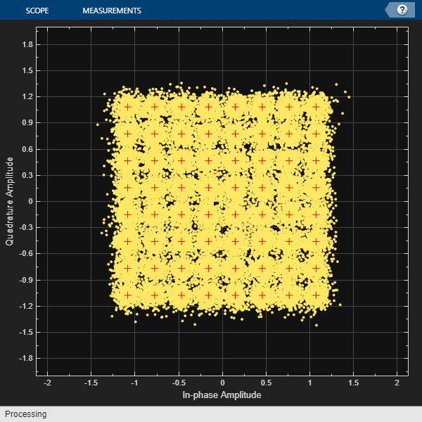
Calculate BER:
ber = errRate(srcBits,double(decBits));
disp(ber(1));
0.0143
To plot a BER curve against a range of EbNo values, use the helperIndoorRayTracingSimulationLoop function to repeat the above single frame processing for up to 300 frames at each EbNo value.
EbNoRange = 27:36;
helperIndoorRayTracingSimulationLoop( ...
    cfgLDPCEnc,cfgLDPCDec,ofdmMod,ofdmDemod,rtChan,errRate, ...
    modOrder,numCodewordsPerFrame,EbNoRange);

Conclusion and Further Exploration
This example shows how to build a deterministic channel model using ray tracing results in an indoor conference room. Link-level simulations using LDPC and MIMO-OFDM techniques were performed for the channel model and BER results were plotted.
Further exploration includes but not limits to:
Different 3-D maps and/or surface materials
Different transmitter and/or receiver site positions
Different transmit and/or receive antenna array specifications
Different transmit and/or receive antenna array orientations
Higher number of reflections for the SBR ray tracing method
Transmit and/or receive beamforming
Appendix
This example uses the following helper functions:
helperIndoorRayTracingRxProcessing.mhelperIndoorRayTracingSimulationLoop.mhelperIndoorRayTracingWaveformGen.mhelperViewArray.m
function H = lclPCM
% Parity-check matrix of a rate 1/2 LDPC code from the IEEE 802.11 standard
H = ldpcQuasiCyclicMatrix(81,...
    [-1 57 -1 -1 -1 -1 -1 -1 -1 50 -1 -1 11 -1 -1 -1 50 -1 -1 -1 -1 79 -1 -1  1 -1  0 -1 -1 -1 -1 -1 -1 -1 -1 -1 -1 -1 -1 -1 -1 -1 -1 -1 -1 -1 -1 -1
     57 -1 -1 -1 -1 -1 -1 -1 50 -1 -1 -1 -1 11 -1 -1 -1 50 -1 -1 79 -1 -1 -1 -1  1 -1  0 -1 -1 -1 -1 -1 -1 -1 -1 -1 -1 -1 -1 -1 -1 -1 -1 -1 -1 -1 -1
     -1  3 -1 -1 -1 28 -1 -1 -1  0 -1 -1 -1 -1 -1 -1 55 -1 -1  7 -1 -1 -1 -1 -1 -1  0 -1  0 -1 -1 -1 -1 -1 -1 -1 -1 -1 -1 -1 -1 -1 -1 -1 -1 -1 -1 -1
      3 -1 -1 -1 28 -1 -1 -1  0 -1 -1 -1 -1 -1 -1 -1 -1 55  7 -1 -1 -1 -1 -1 -1 -1 -1  0 -1  0 -1 -1 -1 -1 -1 -1 -1 -1 -1 -1 -1 -1 -1 -1 -1 -1 -1 -1
     30 -1 -1 -1 -1 -1 -1 -1 -1 24 37 -1 -1 -1 -1 -1 56 -1 -1 14 -1 -1 -1 -1 -1 -1 -1 -1  0 -1  0 -1 -1 -1 -1 -1 -1 -1 -1 -1 -1 -1 -1 -1 -1 -1 -1 -1
     -1 30 -1 -1 -1 -1 -1 -1 24 -1 -1 37 -1 -1 -1 -1 -1 56 14 -1 -1 -1 -1 -1 -1 -1 -1 -1 -1  0 -1  0 -1 -1 -1 -1 -1 -1 -1 -1 -1 -1 -1 -1 -1 -1 -1 -1
     62 -1 53 -1 -1 -1 -1 -1 -1 53 -1 -1 -1 -1  3 -1 35 -1 -1 -1 -1 -1 -1 -1 -1 -1 -1 -1 -1 -1  0 -1  0 -1 -1 -1 -1 -1 -1 -1 -1 -1 -1 -1 -1 -1 -1 -1
     -1 62 -1 53 -1 -1 -1 -1 53 -1 -1 -1 -1 -1 -1  3 -1 35 -1 -1 -1 -1 -1 -1 -1 -1 -1 -1 -1 -1 -1  0 -1  0 -1 -1 -1 -1 -1 -1 -1 -1 -1 -1 -1 -1 -1 -1
     -1 40 -1 -1 -1 -1 20 -1 66 -1 -1 -1 -1 -1 -1 22 -1 28 -1 -1 -1 -1 -1 -1 -1 -1 -1 -1 -1 -1 -1 -1  0 -1  0 -1 -1 -1 -1 -1 -1 -1 -1 -1 -1 -1 -1 -1
     40 -1 -1 -1 -1 -1 -1 20 -1 66 -1 -1 -1 -1 22 -1 28 -1 -1 -1 -1 -1 -1 -1 -1 -1 -1 -1 -1 -1 -1 -1 -1, 0 -1  0 -1 -1 -1 -1 -1 -1 -1 -1 -1 -1 -1 -1
      0 -1 -1 -1 -1 -1 -1 -1  8 -1 -1 -1 42 -1 -1 -1 -1 50 -1 -1 -1,-1  8 -1 -1 -1 -1 -1 -1 -1 -1 -1 -1 -1  0 -1  0 -1 -1 -1 -1 -1 -1 -1 -1 -1 -1 -1
     -1  0 -1 -1 -1 -1 -1 -1 -1  8 -1 -1 -1 42 -1 -1 50 -1 -1 -1 -1 -1 -1  8 -1 -1 -1 -1 -1 -1 -1 -1 -1 -1 -1  0 -1  0 -1 -1 -1 -1 -1 -1 -1 -1 -1 -1
     69 -1 79 -1 79 -1 -1 -1 -1 -1 -1 -1 -1 56 -1 -1 52 -1 -1 -1 -1 -1 -1 -1  0 -1 -1 -1 -1 -1 -1 -1 -1 -1 -1 -1  0 -1  0 -1 -1 -1 -1 -1 -1 -1 -1 -1
     -1 69 -1 79 -1 79 -1 -1 -1 -1 -1 -1 56 -1 -1 -1 -1 52 -1 -1 -1 -1 -1 -1 -1  0 -1 -1 -1 -1 -1 -1 -1 -1 -1 -1 -1  0 -1  0 -1 -1 -1 -1 -1 -1 -1 -1
     65 -1 -1 -1 -1 -1 -1 -1 38 -1 57 -1 -1 -1 -1 -1 72 -1 -1 -1 27 -1 -1 -1 -1 -1 -1 -1 -1 -1 -1 -1 -1 -1 -1 -1 -1 -1  0 -1  0 -1 -1 -1 -1 -1 -1 -1
     -1 65 -1 -1 -1 -1 -1 -1 -1 38 -1 57 -1 -1 -1 -1 -1 72 -1 -1 -1 27 -1 -1 -1 -1 -1 -1 -1 -1 -1 -1 -1 -1 -1 -1 -1 -1 -1  0 -1  0 -1 -1 -1 -1 -1 -1
     -1 64 -1 -1 -1 -1 -1 -1 14 -1 52 -1 -1 -1 -1 -1 -1 30 -1 -1 -1 -1 -1 32 -1 -1 -1 -1 -1 -1 -1 -1 -1 -1 -1 -1 -1 -1 -1 -1  0 -1  0 -1 -1 -1 -1 -1
     64 -1 -1 -1 -1 -1 -1 -1 -1 14 -1 52 -1 -1 -1 -1 30 -1 -1 -1 -1 -1 32 -1 -1 -1 -1 -1 -1 -1 -1 -1 -1 -1 -1 -1 -1 -1 -1 -1 -1  0 -1  0 -1,-1,-1 -1
     -1 -1 -1 45 -1 -1 -1 70  0 -1 -1 -1 -1 -1 -1 -1 77 -1  9 -1 -1 -1 -1 -1 -1 -1 -1 -1 -1 -1 -1 -1 -1 -1 -1 -1 -1 -1 -1 -1 -1 -1  0 -1  0 -1 -1 -1
     -1 -1 45 -1 -1 -1 70 -1 -1  0 -1 -1 -1 -1 -1 -1 -1 77 -1  9 -1 -1 -1 -1 -1 -1 -1 -1 -1 -1 -1 -1 -1 -1 -1 -1 -1 -1 -1 -1 -1 -1 -1  0 -1  0 -1 -1
      2 -1 56 -1 -1 -1 -1 57 35 -1 -1 -1 -1 -1 -1 -1 -1 -1 -1 -1 12 -1 -1 -1 -1 -1 -1 -1 -1 -1 -1 -1 -1 -1 -1 -1 -1 -1 -1 -1 -1 -1 -1 -1  0 -1  0 -1
     -1  2 -1 56 -1 -1 57 -1 -1 35 -1 -1 -1 -1 -1 -1 -1 -1 -1 -1 -1 12 -1 -1 -1 -1 -1 -1 -1 -1 -1 -1 -1 -1 -1 -1 -1 -1 -1 -1 -1 -1 -1 -1 -1  0 -1  0
     -1 24 -1 -1 -1 61 -1 -1 -1 60 -1 -1 -1 -1 -1 27 51 -1 -1 -1 -1 -1 16 -1  1 -1 -1 -1 -1 -1 -1 -1 -1 -1 -1 -1 -1 -1 -1 -1 -1 -1 -1 -1 -1 -1  0 -1
     24 -1 -1 -1 61 -1 -1 -1 60 -1 -1 -1 -1 -1 27 -1 -1 51 -1 -1 -1 -1 -1 16 -1  1 -1 -1 -1 -1 -1 -1 -1 -1 -1 -1 -1 -1 -1 -1 -1 -1 -1 -1 -1 -1 -1  0
    ]);
end
Selected Bibliography
[1] Z. Yun, and M. F. Iskander, “Ray tracing for radio propagation modeling: Principles and applications,” IEEE Access, vol. 3, pp. 1089-1100, Jul. 2015.
[2] 3GPP TR 38.901. Study on channel model for frequencies from 0.5 to 100 GHz. 3rd Generation Partnership Project; Technical Specification Group Radio Access Network.
[3] Maltsev, A., et al. Channel Models for 802.11ay. IEEE 802.11-15/1150r9, March 2017.