Validate Gain-Scheduled Control Systems
Tuned gain schedules require careful validation. The tuning process guarantees suitable performance only near each design point. In addition, the tuning ignores dynamic couplings between the plant state variables and the scheduling variables (see Section 4.3, “Hidden Coupling”, in [1]). Best practices for validation include:
Examine tuned gain surfaces to make sure that they are smooth and well-behaved.
Visualize tuning goals against system responses at all design points.
Check linear performance of the tuned control system between design points.
Validate gain schedules in simulation of the full nonlinear system.
Check linear performance on a denser grid of σ values than you used for design. If adequate linear performance is not maintained between design points, you can add more design points and retune.
Perform nonlinear simulations that drive the closed-loop system through its entire operating range. Pay special attention to maneuvers that cause rapid variations of the scheduling variables.
Examine Tuned Gain Surfaces
After tuning, examine the tuned gains as a function of the scheduling variables to make
sure that they are smooth and well-behaved over the operating range. Visualize tuned gain
surfaces using the viewSurf command.
Visualize Tuning Goals
Use tuning-goal plots to visualize your design requirements against the linear response of the tuned control system. Tuning-goal plots show graphically where and by how much tuning goals are satisfied or violated. This visualization lets you examine how close your control system is to ideal performance. It can also help you identify problems with tuning and provide clues on how to improve your design.
For general information about using tuning-goal plots, see
Visualize Tuning Goals. For
gain-scheduled control systems, the tuning-goal plots you generate with viewGoal provide additional information that helps you evaluate how each
tuning goal contributes to the result.
Fixed Tuning Goals
For fixed tuning goals that apply to multiple design points,
viewGoal plots the relevant system response at all those design
points. For instance, suppose that you tune an slTuner interface,
ST, for the rct_CSTR model described in
Gain-Scheduled Control of a Chemical Reactor.
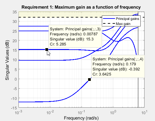
You can use viewGoal to see how well each of the five design points
of that example satisfies the gain goal R3. The resulting plot shows
the relevant gain profile at all five design points. Click any of the gain lines for a
display that shows the corresponding value of the scheduling variable
Cr.
viewGoal(R3,ST)
Varying Tuning Goals
Varying goals that you create using varyingGoal apply a different target response at each design point. When you
use viewGoal to examine a varying goal, the plot initially displays the target and tuned
responses at the first design point in the design grid. For instance, suppose that you
tune a control system ST over a design grid of two scheduling
variables, using a varying goal Rv that varies across the entire grid.
After tuning, examine Rv.
viewGoal(Rv,ST)

Click CHANGE to open sliders that let you select a design point at which to view the target and tuned responses.

Check Linear Performance
In addition to examining linear responses associated with tuning goals, check other linear responses of the system to make sure that the behavior is suitable. You can do so by extracting and plotting system responses as described generally in Validate Tuned Control System.
For gain-scheduled systems, it is good practice to check linear performance on a denser grid of operating points than you used for design. If the system does not maintain adequate linear performance between design points, then you can add more design points and retune.
Validate Gain Schedules in Nonlinear System
Because systune tunes gain schedules against a linearization
obtained at each design point, it is important to test the tuning results in simulation of
the full nonlinear system. Perform nonlinear simulations that drive the closed-loop system
through its entire operating range. Pay special attention to maneuvers that cause rapid
variations of the scheduling variables.
After tuning an slTuner interface, use writeBlockValue (Simulink Control Design) to write tuned controller parameters to the Simulink® model for such simulation. This command can write tuned gain schedules to
lookup table blocks, Matrix Interpolation blocks, and MATLAB
Function blocks for which you have specified a tunableSurface
parameterization.
Lookup Tables
For lookup table blocks and Matrix Interpolation blocks,
writeBlockValue automatically evaluates the tuned gain surface at
the breakpoints specified in the block. These breakpoints do not need to be the same as
the design points used for tuning. Because the tunableSurface
describes the gain schedule in parametric form, writeBlockValue can
evaluate the gain at any scheduling-variable value.
If you have retuned a subset of design points, you can use writeLookupTableData (Simulink Control Design) to update a portion of the lookup-table data while
leaving the rest intact.
MATLAB Function Blocks
For gain schedules implemented as MATLAB Function blocks,
writeBlockValue automatically generates MATLAB® code and pushes it to the block. The generated MATLAB function takes the scheduling variables and returns the gain value given by
the tuned parametric expression of the tunableSurface. To see this
MATLAB code for a particular gain surface, use the codegen
command.
References
[1] Rugh, W.J., and J.S. Shamma, "Research on Gain Scheduling", Automatica, 36 (2000), pp. 1401-1425.
See Also
viewSurf | codegen | writeBlockValue (Simulink Control Design) | writeLookupTableData (Simulink Control Design) | viewGoal