Unreal Engine Simulation for Automated Driving
Automated Driving Toolbox™ provides a co-simulation framework that models driving algorithms in Simulink® and visualizes their performance in a virtual simulation environment. This environment uses the Unreal Engine® from Epic Games®.
Note
Simulating models in the 3D visualization environment requires Simulink 3D Animation™.
Simulink blocks related to the simulation environment can be found in the Automated Driving Toolbox > Simulation 3D block library. These blocks provide the ability to:
Configure scenes in the simulation environment.
Place and move vehicles within these scenes.
Set up camera, radar, and lidar sensors on the vehicles.
Simulate sensor outputs based on the environment around the vehicle.
Obtain ground truth data for semantic segmentation and depth information.
This simulation tool is commonly used to supplement real data when developing, testing, and verifying the performance of automated driving algorithms. In conjunction with a vehicle model, you can use these blocks to perform realistic closed-loop simulations that encompass the entire automated driving stack, from perception to control.
For more details on the simulation environment, see How Unreal Engine Simulation for Automated Driving Works.
Unreal Engine Simulation Blocks
To access the Automated Driving Toolbox > Simulation 3D library, at the MATLAB® command prompt, enter drivingsim3d.
Scenes
To configure a model to co-simulate with the simulation environment, add a Simulation 3D Scene Configuration block to the model. Using this block, you can choose from a set of prebuilt scenes where you can test and visualize your driving algorithms. You can also use this block to control the sun position and weather conditions in the scene. The following image is from the Large Parking Lot scene.

The toolbox includes these default scenes:
| Scene | Description |
|---|---|
| Straight Road | Straight road segment |
| Curved Road | Curved, looped road |
| US City Block | City block with intersections, barriers, and traffic lights |
| Large Parking Lot | Parking lot with parked cars, cones, curbs, and traffic signs |
| Empty Grass | Empty grass environment |
The toolbox also includes these additional scenes which you can install on-demand using the Scene Name parameter of the Simulation 3D Scene Configuration block:
| Scene | Description |
|---|---|
| Parking Lot | Empty parking lot |
| Double Lane Change | Straight road with traffic barrels and traffic signs that are set up for executing a double lane change maneuver |
| Open Surface | Flat, black pavement surface with no road objects |
| US Highway | Highway with cones, barriers, traffic lights, and traffic signs |
| Virtual Mcity | City environment that represents the University of Michigan proving grounds (see Mcity Test Facility); includes cones, barriers, an animal, traffic lights, and traffic signs |
| ZalaZONE Automotive Proving Ground Smart City | Smart city environment that represents the ZalaZONE proving ground in Hungary. |
If you have the Automated Driving Toolbox Interface for Unreal Engine Projects support package, then you can modify these scenes or create new ones. For more details, see Customize Unreal Engine Scenes for Automated Driving.
Vehicles
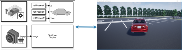
To define a virtual vehicle in a scene, add a Simulation 3D Vehicle with Ground Following block to your model. Using this block, you can control the movement of the vehicle by supplying the X, Y, and yaw values that define its position and orientation at each time step. The vehicle automatically moves along the ground.
You can also specify the color and type of vehicle. The toolbox includes these vehicle types:
Sensors
You can define virtual sensors and attach them at various positions on the vehicles. The toolbox includes these sensor modeling and configuration blocks.
| Block | Description |
|---|---|
| Simulation 3D Camera | Camera model with lens. Includes parameters for image size, focal length, distortion, and skew. |
| Simulation 3D Fisheye Camera | Fisheye camera that can be described using the Scaramuzza camera model. Includes parameters for distortion center, image size, and mapping coefficients. |
| Simulation 3D Lidar | Scanning lidar sensor model. Includes parameters for detection range, resolution, and fields of view. |
| Simulation 3D Probabilistic Radar | Probabilistic radar model that returns a list of detections. Includes parameters for radar accuracy, radar bias, detection probability, and detection reporting. It does not simulate radar at an electromagnetic wave propagation level. |
| Simulation 3D Probabilistic Radar Configuration | Configures radar signatures for all actors detected by the Simulation 3D Probabilistic Radar blocks in a model. |
| Simulation 3D Vision Detection Generator | Camera model that returns a list of object and lane boundary detections. Includes parameters for modeling detection accuracy, measurement noise, and camera intrinsics. |
For more details on choosing a sensor, see Choose a Sensor for Unreal Engine Simulation.
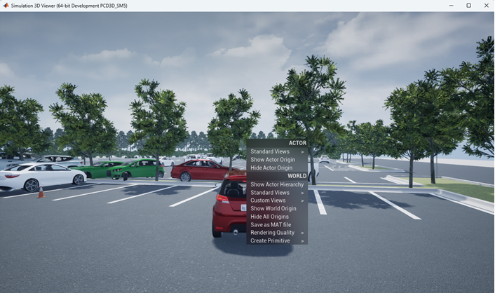
Interact with Unreal Engine Scene and Actors
During simulation, right-click the actor to display the context menu for actor and world. You can only interact with the properties of actors created using these blocks:
This table summarizes the Actor options in the context menu:
| Actor Option | Description |
|---|---|
Standard Views | List the standard views of the actor.
Note When simulating models, this option is available when
Scene view is set to
|
Show Actor Origin | Display the axes of the default coordinate system at actor origin. |
Hide Actor Origin | Hide the coordinate axes of the actor. |
During simulation, you can right-click anywhere in the 3-D environment to display the context menu for the world. This table summarizes the World options for the 3-D environment:
| World Option | Description |
|---|---|
Show Actor Hierarchy | Open the Actor Hierarchy to view the hierarchical structure of the actors in the 3D environment during simulation. You can double-click on the actor name to display the perspective view of the actor and attach the virtual camera to the actor. You can also right-click on the actor name to display the context menu for actor and world. |
Standard Views | List the standard views of the 3D environment.
Note When simulating models, this option is available when
Scene view is set to |
Custom Views | List the views created to view the 3D environment. |
Show World Origin | Display the axes of the default coordinate system at world origin. |
Hide All Origins | Hide the coordinate axes of all actors and world origin. |
Save as MAT file | Save the 3D environment as a MAT file, including all the actors in the world. |
Algorithm Testing and Visualization
Automated Driving Toolbox simulation blocks provide the tools for testing and visualizing path planning, vehicle control, and perception algorithms.
Path Planning and Vehicle Control
You can use the Unreal Engine simulation environment to visualize the motion of a vehicle in a
prebuilt scene. This environment provides you with a way to analyze the performance
of path planning and vehicle control algorithms. After designing these algorithms in
Simulink, you can use the drivingsim3d library to visualize
vehicle motion in one of the prebuilt scenes.
For an example of path planning and vehicle control algorithm visualization, see Visualize Automated Parking Valet Using Unreal Engine Simulation.
Perception
Automated Driving Toolbox provides several blocks for detailed camera, radar, and lidar sensor modeling. By mounting these sensors on vehicles within the virtual environment, you can generate synthetic sensor data or sensor detections to test the performance of your sensor models against perception algorithms. For an example of generating radar detections, see Simulate Vision and Radar Sensors in Unreal Engine Environment.
You can also output and visualize ground truth data to validate depth estimation algorithms and train semantic segmentation networks. For an example, see Depth and Semantic Segmentation Visualization Using Unreal Engine Simulation.
Localization
Developing a localization algorithm and evaluating its performance in varying conditions is a challenging task. One of the biggest challenges is obtaining ground truth. Although you can capture ground truth using expensive, high-precision inertial navigation systems (INS), virtual simulation is a cost-effective alternative. The use of simulation enables testing under a variety of scenarios and sensor configurations. It also enables a rapid development iteration, and provides precise ground truth. For an example to develop and evaluate a lidar localization algorithm using synthetic lidar data from the Unreal Engine simulation environment, see Lidar Localization with Unreal Engine Simulation.
Closed-Loop Systems
After you design and test a perception system within the simulation environment, you can use this system to drive a control system that actually steers a vehicle. In this case, rather than manually set up a trajectory, the vehicle uses the perception system to drive itself. By combining perception and control into a closed-loop system in the 3D simulation environment, you can develop and test more complex algorithms, such as lane keeping assist and adaptive cruise control.
For an example of a closed-loop system in the Unreal Engine environment, see Highway Lane Following.