dsp.DCBlocker
Block DC component (offset) from input signal
Description
The dsp.DCBlocker
System object™ removes the DC offset from each channel (column) of the input signal. The
operation runs over time to continually estimate and remove the DC offset.
To block the DC component of the input signal:
Create the
dsp.DCBlockerobject and set its properties.Call the object with arguments, as if it were a function.
To learn more about how System objects work, see What Are System Objects?
The object supports C/C++ code generation and SIMD code generation under certain conditions. For more information, see Code Generation.
Creation
Description
dcblker = dsp.DCBlockerdcblker, to block the DC component from each channel
(column) of the input signal.
dcblker = dsp.DCBlocker(PropertyName=Value)NormalizedBandwidth to 0.004.
Properties
Usage
Description
dcblkerOut = dcblker(input)
Input Arguments
Output Arguments
Object Functions
To use an object function, specify the
System object as the first input argument. For
example, to release system resources of a System object named obj, use
this syntax:
release(obj)
Examples
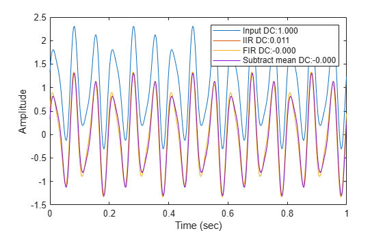
Remove the DC component of an input signal using the IIR, FIR, and subtract mean estimation algorithms.
Create a signal composed of a 15 Hz tone, a 25 Hz tone, and a DC offset.
t = (0:0.001:100)';
x = sin(30*pi*t) + 0.33*cos(50*pi*t) + 1;
Create three DC blocker objects for the three estimation algorithms.
dc1 = dsp.DCBlocker(Algorithm="IIR",Order=6);
dc2 = dsp.DCBlocker(Algorithm="FIR",Length=100);
dc3 = dsp.DCBlocker(Algorithm="Subtract mean");
For each second of time, pass the input signal through the DC blockers. By implementing the DC blockers in 1-second increments, you can observe differences in the convergence times.
for idx = 1 : 100
    range = (1:1000) + 1000*(idx-1);
    y1 = dc1(x(range));          % IIR estimate
    y2 = dc2(x(range));          % FIR estimate
    y3 = dc3(x(range));          % Subtract mean
end
Plot the input and output data for the three DC blockers for the first second of time, and show the mean value for each signal. The mean values for the three algorithm types show that the FIR and Subtract mean algorithms converge more quickly.
plot(t(1:1000),x(1:1000), ...
    t(1:1000),y1, ...
    t(1:1000),y2, ...
    t(1:1000),y3);
xlabel("Time (sec)")
ylabel("Amplitude")
legend(sprintf("Input DC:%.3f",mean(x)), ...
    sprintf("IIR DC:%.3f",mean(y1)), ...
    sprintf("FIR DC:%.3f",mean(y2)), ...
    sprintf("Subtract mean DC:%.3f",mean(y3)));
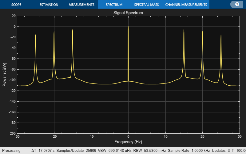
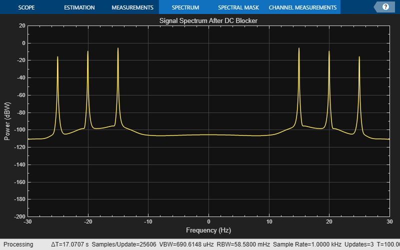
Compare the spectrum of an input signal with a DC offset to the spectrum of the same signal after applying a DC blocker. Enable the DC blocker to use the FIR estimation algorithm.
Create an input signal composed of three tones and that has a DC offset of 1. Set the sampling frequency to 1 kHz and set the signal duration to 100 seconds.
fs = 1000;
t = (0:1/fs:100)';
x = sin(30*pi*t) + 0.67*sin(40*pi*t) + 0.33*sin(50*pi*t) + 1;
Create a DC blocker object that uses the FIR algorithm to estimate the DC offset.
dcblker = dsp.DCBlocker(Algorithm="FIR",Length=100);
Create a spectrum analyzer with power units set to dBW and a frequency range of [-30 30] to display the frequency response of the input signal. Using the clone function, create a second spectrum analyzer to display the response of the output. Then, use the Title property of the spectrum analyzers to label them.
hsa = spectrumAnalyzer(SampleRate=fs, ...
    Method="welch",...
    AveragingMethod="exponential",...
    SpectrumUnits="dBW",FrequencySpan="start-and-stop-frequencies",...
    StartFrequency=-30,StopFrequency=30,YLimits=[-200 20],...
    Title="Signal Spectrum");

hsb = clone(hsa);
hsb.Title = "Signal Spectrum After DC Blocker";
Pass the input signal, x, through the DC blocker to generate the output signal, y.
y = dcblker(x);
Use the first spectrum analyzer to display the frequency characteristics of the input signal. The tones at 15, 20, and 25 Hz, and the DC component, are clearly visible.
hsa(x)
Use the second spectrum analyzer to display the frequency characteristics of the output signal. The DC component has been removed.
hsb(y)
Algorithms
References
[1] Nezami, M. “Performance Assessment of Baseband Algorithms for Direct Conversion Tactical Software Defined Receivers: I/Q Imbalance Correction, Image Rejection, DC Removal, and Channelization.” MILCOM, 2002.