For Loop
This example shows how to implement a for loop construct by using Simulink® blocks, Stateflow® Charts, and MATLAB® Function blocks.
C Construct
y1 = 0;
for(inx = 0; inx <10; inx++)
{
  y1 = u1[inx] + y1;
}
Modeling Pattern for For Loop: For-Iterator Subsystem block
One method for creating a for loop is to use a For Iterator Subsystem block from the Simulink > Ports & Subsystems library.
1. Open example model ex_for_loop_SL.
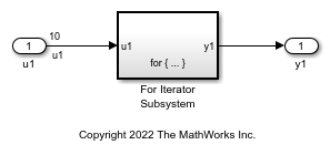
The model contains a For Iterator Subsystem block that repeats execution of the contents of the subsystem during a simulation time step.
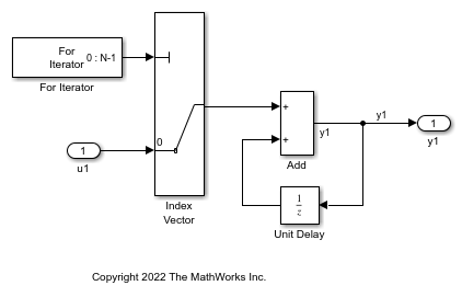
Observe the following settings in the model:
Open the For Iterator block. In the Block Parameters dialog box, the Index-mode parameter is
Zero-basedand the Iteration limit parameter is 10.Open the Unit Delay block. In the Block Parameters dialog box, the Initial Conditions parameter is 0. This parameter initializes the state to zero.
2. To build the model and generate code, press Ctrl+B.
The code implementing the for loop is in the ex_for_loop_SL_step function in ex_for_loop_SL.c:
/* External inputs (root inport signals with default storage) */
ExternalInputs U;

/* External outputs (root outports fed by signals with default storage) */
ExternalOutputs Y;

/* Model step function */
void ex_for_loop_SL_step(void)
{
  int32_T rtb_y1;
  int32_T s1_iter;

  /* Outputs for Iterator SubSystem: '<Root>/For Iterator Subsystem' incorporates:
   *  ForIterator: '<S1>/For Iterator'
   */
  for (s1_iter = 0; s1_iter < 10; s1_iter++) {
    /* Sum: '<S1>/Add' incorporates:
     *  Inport: '<Root>/u1'
     *  MultiPortSwitch: '<S1>/Index Vector'
     *  UnitDelay: '<S1>/Unit Delay'
     */
    rtb_y1 = U.u1[s1_iter] + DWork.UnitDelay_DSTATE;

    /* Update for UnitDelay: '<S1>/Unit Delay' */
    DWork.UnitDelay_DSTATE = rtb_y1;
  }

  /* End of Outputs for SubSystem: '<Root>/For Iterator Subsystem' */

  /* Outport: '<Root>/y1' */
  Y.y1 = rtb_y1;
}
Modeling Pattern for For Loop: Stateflow Chart
1. Open example model ex_for_loop_SF.
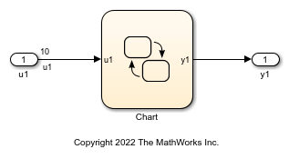
The chart contains a For loop decision pattern that you add by right clicking inside the chart > Add Pattern in Chart > Loop > For.
2. To build the model and generate code, press Ctrl+B.
The code implementing the for loop is in the ex_for_loop_SF_step function in ex_for_loop_SF.c:
/* External inputs (root inport signals with default storage) */
ExternalInputs U;

/* External outputs (root outports fed by signals with default storage) */
ExternalOutputs Y;

/* Model step function */
void ex_for_loop_SF_step(void)
{
  int32_T inx;

  /* Chart: '<Root>/Chart' */
  for (inx = 0; inx < 10; inx++) {
    /* Outport: '<Root>/y1' incorporates:
     *  Inport: '<Root>/u1'
     */
    Y.y1 += U.u1[inx];
  }

  /* End of Chart: '<Root>/Chart' */
}
Modeling Pattern for For Loop: MATLAB Function block
1. Open example model ex_for_loop_ML.
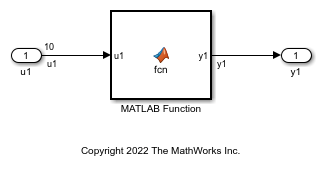
The MATLAB Function Block contains this function:
function y1 = fcn(u1)

y1 = 0;

for inx=1:10
    y1 = u1(inx) + y1 ;
end
2. To build the model and generate code, press Ctrl+B.
The code implementing the for loop is in the ex_for_loop_ML_step function in ex_for_loop_ML.c:
/* Exported block signals */
real_T u1[10];                         /* '<Root>/u1' */
real_T y1;                             /* '<Root>/MATLAB Function' */

/* Model step function */
void ex_for_loop_ML_step(void)
{
  int32_T inx;

  /* MATLAB Function: '<Root>/MATLAB Function' incorporates:
   *  Inport: '<Root>/u1'
   */
  y1 = 0.0;
  for (inx = 0; inx < 10; inx++) {
    y1 += u1[inx];
  }

  /* End of MATLAB Function: '<Root>/MATLAB Function' */
}