PMSM Rs Estimator
Estimate stator resistance (Rs) of permanent magnet synchronous motor (PMSM)
Since R2023a
Libraries:
Motor Control Blockset /
Parameter Estimation /
PMSM Parameter Estimation
Description
The PMSM Rs Estimator block computes the stator resistance of a PMSM using the phase currents, DC voltage across the motor, and the test configuration elements.
The block injects two voltages V1 and V2 for each phase and measures the respective current responses I1 and I2 to estimate each phase resistance. It then estimates the motor resistance by averaging the three phase resistances.
Examples
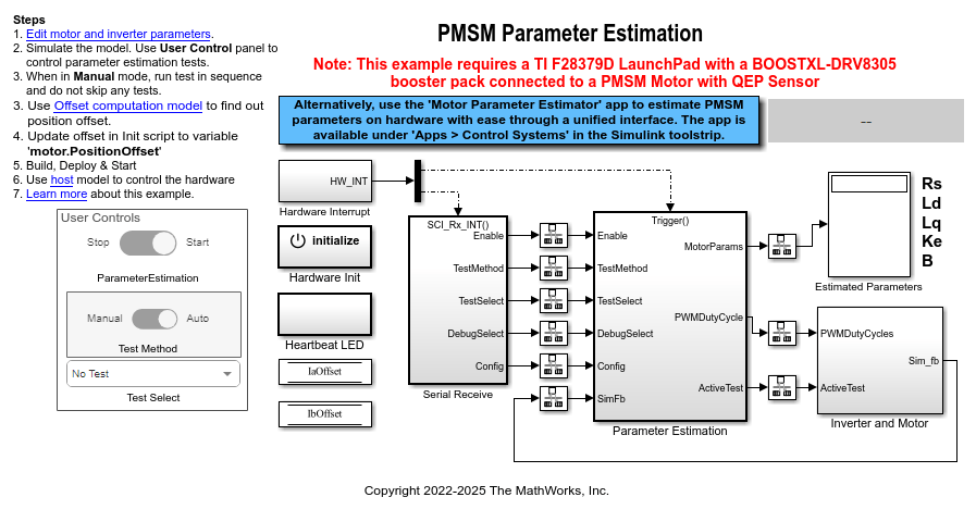
Estimate PMSM Parameters Using Parameter Estimation Blocks
Uses the parameter estimation blocks provided by Motor Control Blockset™ to estimate these parameters of a permanent magnet synchronous motor (PMSM) with a quadrature encoder sensor:
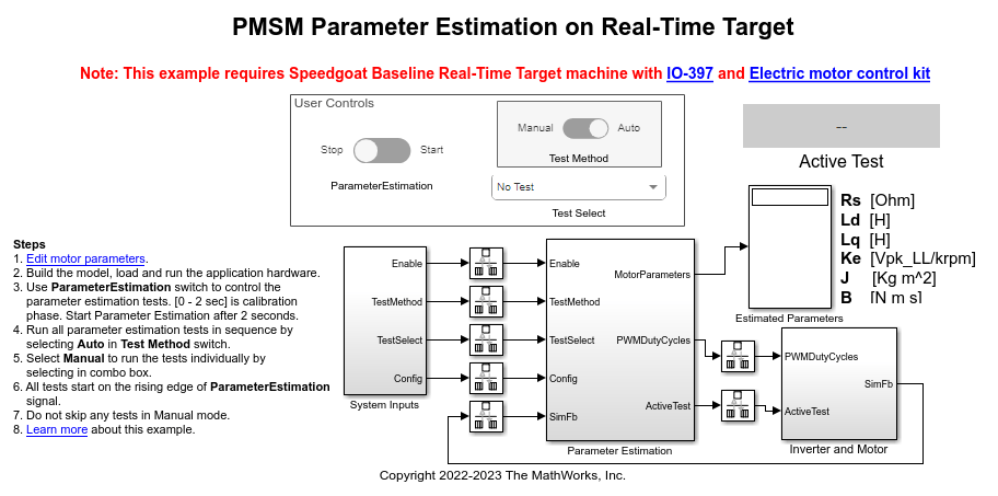
Estimate PMSM Parameters Using Parameter Estimation Blocks on Real-Time Systems
Uses the parameter estimation blocks provided by Motor Control Blockset™ to estimate these parameters of a permanent magnet synchronous motor (PMSM):